Transcription of 空調機璮熱交換器の高性能化における研究開発 Research and …
1 2007 , . Copyright 2007 .. Research and Development on Improvement in Performance of heat Exchangers for Air-conditioners . Yutaka Shibata, Daikin Industries, Ltd., 1304 Kanaoka-cho, Kita-ku, Sakai, Osaka heat exchangers for air-conditioners generally consist of aluminum fins and copper tubes. The performance of the heat exchangers had been improved by heat transfer enhancement on the fins and on the tubes for several decades. In recent years, however, the conventional methods of heat transfer enhancement are coming close to the limit due to some problems in practical use.
2 And the heat exchangers have various factors that can deteriorate the performance. This paper shows some techniques that have been developed to improve the performance of the heat exchangers and, additionally, new trials by which more remarkable heat transfer enhancement is intended. Key Words: heat exchanger , heat Transfer, Air Conditioning, Refrigerant, Energy Saving . CO2 Table 1 1990 . 25% (1) .. 1999 .. 2000 .. K . Table 1 .. 7 .. 30 . K A 4 .. Table 1 Inside layout of the indoor units of residential air-conditioners(1).. heat exchanger for air-conditioners.
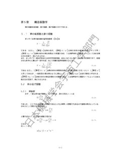
3 Q[ ] K 1/100 . [W/m2K] A [m2] 5 . T [K] Q = F K A T . F . (1). 1 . T K A .. A .. (10)-(19) . (10) .. Fins of heat exchangers for indoor units(1). 1mm .. (2)-(8) (4) .. l2/l1 Nu . Cf (11) . Nu .. jh/Cf . l2/l1= . l2/l1= . Webb(9) .. Multi bended heat exchanger . Bow shaped heat exchanger . (21). Cross sections of heat exchangers . (a) Basic louvered fin. (b) Parallel louvered fin. (c) Inclined louvered fin. (d) Offset fin. Analytical models and computational domains of fins(4). (a). (b). (c). (d). Heating mode. Cooling mode. (21). Air flow rate and heat capacity . Table 1.
4 (20) - (22) (21) .. Fig. 4 Nu and Cf for Optimum Condition for . each fin(4). each fin(4).. Herringbone tube. Inner grooved tube. Photos and illustrations of tubes.. (1) .. 3 50%. (23) . heat transfer coefficient Ratio of heat transfer coefficient or pressure drop (Evaporation) heat transfer coefficient of R22 and R407C(24). heat transfer coefficient (Condensation). Pressure drop Asymmetrical Grooved Inductively Welded . Grooved Trapezoid / Slim Cross-Grooved Grooved Trapezoid . Grooved Grooved Trapezoid / Slim / High- fin . Triangular Circumferential distribution of liquid layer thickness(25).
5 Plane 1980 1990 1995 2000. Tubes of heat exchangers(1). HCFC.. R22 HFC . R407C Evaporation. R410A R22 R407C . R410A.. 2000 . R407C R410A .. Condensation. W Tube wall temperature and heat transfer coefficient(25). W . (24) - (28) (25) (24) R22 . R407C W . x R407C . R22 R407C . R407C W .. (26)-(28) . (29) .. (24) R407C W . W .. W .. (30) W .. heat transfer coefficient. Pressure drop. heat transfer characteristics of tubes(31). (31) .. W .. (32) W .. R22 R410A .. (33)(34) .. Shibata (35). (36) 2 .. (37) 4 . 2 (35) . heat transfer coefficient. Pressure drop.. heat transfer characteristics of tubes(24).
6 Asymmetrical inner Cross-grooved tube . grooved tube(30). (Micro-notched tube) (31).. Photos of conventional distributors. (a) Conventional branch pipe. (b) New type distributor (cross section). Photos of distributors(39). Conventional type New type 18 18. Upper pass Upper pass 16 16. Lower pass Lower pass Twall , . Twall , . 14 14. 12 12. 10 10. 8 8. 0 2 4 6 8 10 0 2 4 6 8 10. Length Length Temperature distribution(39). Instantaneous visualized images and illustrations(35).. 21(b).. Refrigerant .. Optimization of a distributor(37).. (38) .. (39) . (35) .. (40).
7 2 . (41)-(45) . (44) .. (44) .. Previous type. New type.. Cross sections of distributors(38).. (22) . 5 7 1 .. 2 .. Simulation model for a heat exchanger (44).. 18% . Indoor heat exchanger for a residential air-conditioner(44). Array of different diameter tubes(22). COP .. 2000 .. (46) (47) .. (1) .. 9 .. COP .. (48) .. Auxiliary Effect of auxiliary (49) . heat exchanger (1). heat exchanger (1).. (a) .. (56) .. (b) .. (50)(51) . (52) .. Parallel flow type heat exchanger (55).. (53) (54) .. (a) Draining along tubes. (b) Draining along corrugated fins. Illustrations of draining pattern(56).
8 Kim (57) .. Fin with vortex Finned-tube bundles with . generators(53). winglets(54). 20% .. (55) .. Aluminum form metal(57).. (30) 38 (2001), 887-888. (31) . (1998), 81-84. (32) (2006), 59-60. (33) . (1996), 169-172. (34) 30 . (1996), 141-144. (35) Shibata, Y., Ebisu, T., Asano, H., Takanaka, N., Fujii, T. and Matsubayashi, M., Proc. of The 3rd Int. Conf. on Multiphase Flow '98 (1998) (CD-ROM). (1) 75-878 (2000), 1052-1057. (36) Asano, H., Takenaka, N., Fujii, T., Ono, A., Motomura, Y., (2) B 55-519 (1989), 3449-3456. Murata, Y., Mochiki, K., Taguchi, A., Tsuruno, A.
9 And (3) B 55-519 (1989), 3457-3461. Matsubayashi, M., Proc. of The 2nd Int. Conf. on (4) B 55-519 (1989), 3462-3466. Multiphase Flow '95 (1995), IN2-27 - IN2-32. (5) B 57-544 (1991), 4223-4228. (37) (2006), (6) B 55-509 (1989), 221-226. 367-370. (7) B 56-531 (1990), 3279-3283. (38) 34 . (8) B 57-542 (1991), 3476-3482. (2000), 89-92. (9) Webb, R. L., Principles of Enhanced heat Transfer, John (39) (2004), Wiley & Sons, Inc. (1994), 87-124. 27-28. (10) 33 (40) 29 . (1996), 527-528. (1995), 65-68. (11) 35-2 (1998), (41) 33 (1996), 100-103. 529-530. (12) B 69-677 (42) 32.
10 (2003), 94-99. (1998), 53-56. (13) B 70-694 (2004), (43) 34 (2000), 1541-1546. 13-16. (14) B 64-618 (44) 41 (2004), (1998), 534-541. 81-82. (15) B 65-634 (1999), (45) B 73-727 (2007), 796-802. 2077-2084. (46) 44-502 (1969), 731-737. (16) B 67-653 (2001), 120-127. (47) . (17) 23-2 (1992), 34-36. (2006), 175-185. (48) 50-2 (2000), (18) 23-4 (2006), 19-21. 437-446. (49) 44 . (19) 41 (2004), (2007), 637-638. 317-318. (50) 29 . (20) (1995), 57-60. (1995), 161-164. (51) 40 . (21) 31 (2003), 491-492. (1997), 65-68. (52) (2002), 285-288. (22) (2006), 73-74. (53) B 68-665 (2002), 188-193.