Transcription of Resistive circuit analysis. Kirchhoff’s Laws Figure 1
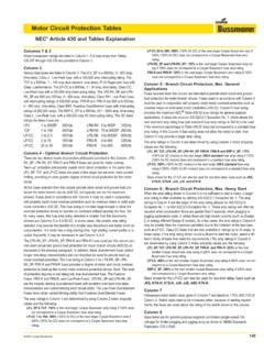
1 Resistive circuit analysis. Kirchhoff s Laws Fundamentals of DC electric circuits. A simple model that we can use as a starting point for discussing electronic circuits is given on Figure 1. iSourceLoadiVoltageacrosssourseVsResista nceinternal toloadRL Figure 1. Fundamental circuit model This circuit is made up of a source which provides a voltage across its terminals, labeled and a loadSV connected to the source which presents a resistance LR to the current flowing as indicated around a closed loop. i In order to characterize the operation of this circuit we must determine: What voltage does the source provide as a function of current i? SV What resistance LR does the load present? In order to completely define the problem we have to establish the relationship between the voltage , the resistance SVLR and the current i. Before proceeding let s define the physical significance of these new physical variables and establish ways to represent them.
2 Current i The current results from the flow of electric charge around the closed loop shown on Figure 1. Electrons are electrically (negatively) charged particles and their flow in conductors such as wires results in electric current. i The current, , is equal to the amount of charge, Q, passing through a cross-section per second and it is expressed as Spring 2006. Chaniotakis and Cory 1 dQidt= ( ) The unit of charge is the Coulomb. One Coulomb is equivalent to x 1018 electrons. The unit for current is the ampere, A. One ampere = 1 Voltage In order to move electrons along a conductor some amount of work is required. The work required must be somehow supplied by an electromotive force usually provided by a battery or similar device. This electromotive force is referred to as the voltage or potential difference between two points or across an element.
3 By representing an element with the block diagram shown on Figure 2, the voltage across the element represents the potential difference between terminals a and b. Mathematically the voltage is given by abv abdWvdQ= ( ) where work (W) is measured in Joules and the charge (Q) in Coulombs. The voltage is measured in volts (V) and JouleNewton meter1 volt 1 =1 CoulombAmpere second . +-abelementvab Figure 2. Voltage across an element The positive (+) and negative (-) signs shown on Figure 2 define the polarity of the voltage . With this definition, represents the voltage at point a relative to point b. Equivalently we may also say that the voltage at point a is volts higher than the voltage at point b. abvabvabv 1 The SI system of units is based on the following seven base units: Length: m Mass: kg Time: s Thermodynamic temperature: K Amount of substance: mol Luminous intensity: cd Current A The purpose for this small diversion is to remind us of the power of dimensional analysis in engineering.
4 Spring 2006. Chaniotakis and Cory 2 /iv curves The two dynamical variables of electronic circuits are current and voltage. It is useful therefore to explore the characteristic relationship between these for various circuit elements. The relationship between voltage and current for an element or for an entire circuit as we will explore shortly is fundamental in circuit design and electronics. We will start this exploration by looking at the space of the two most fundamental sources: the voltage source and the current source. /iv Ideal DC voltage sources The most common voltage source is a battery. The voltage provided by a battery is constant in time and it is called DC voltage. In its ideal implementation the battery provides a specific voltage at all times and for all loads. The common symbols for a battery are shown on Figure 3. +-Vs +-Vs Figure 3. Battery symbols The curve of an ideal battery is: /iv vi0Vs As the curve shows, regardless of the current flowing through the battery, the voltage across the battery remains constant.
5 The actual amount of current that is provided by the battery depends on the circuit that is connected to the battery. /iv This is not a realistic model of a battery. Real batteries contain small internal resistors resulting in a modification of the curve. We will look at these non-ideal effects in more detail shortly. /iv Spring 2006. Chaniotakis and Cory 3 Ideal DC current sources The current source is a device that can provide a certain amount of current to a circuit . The symbol for a DC current source and the characteristic curve of an ideal current source are shown on Figure 4. /iv Is (a) viIs0 (b) Figure 4. (a) Symbol of current source and (b) characteristic curve of ideal current source. /iv Ideal resistor An ideal resistor is a passive, linear, two-terminal device whose resistance follows Ohm s law given by, viR= ( ) which states that the voltage across an element is directly proportional to the current flowing through the element.
6 The constant of proportionality is the resistance R provided by the element. The resistance is measured in Ohms, , and V1 = 1A ( ) The symbol for a resistor is, R Notice that there is no specific polarity to a physical resistor, the two leads (terminals) are equivalent. The circuit shown on Figure 5 consists of a voltage source and a resistor. These two elements are connected together with wires which are considered to be ideal. The current flowing through the resistor is given by SViR= ( ) Spring 2006. Chaniotakis and Cory 4 +-VsRi Figure 5. Simple Resistive circuit . The curve for a resistor is a straight line (the current is directly proportional to the voltage). The slope of the straight line is /iv1R (see Figure 6) For convenience we define the conductance (G) of a circuit element as the inverse of the resistance.
7 1ivGvR== ( ) The SI unit of conductance is the siemens (S) 1 VS== ( ) The most important use of curves is to characterize a component or an entire circuit as we will see later. The curve of the resistor shown on Figure 6 describes how that resistor will behave for any voltage or current. We can therefore use the curve to find the operating points of circuits. For our circuit ( Figure 5) the voltage is set by the battery at and thus the operating point may be determined as shown graphically on Figure 6. /iv/iv/ivSV The power of this method should not be dismissed just because of its apparent simplicity. The curve is one of the most powerful tools for circuit analysis and we will use it extensively in characterizing circuits and electronic components.
8 /iv vi0 VsVs/Rslope is1/Roperating point Figure 6. curve of a resistor /iv Spring 2006. Chaniotakis and Cory 5 The linear relationship of the resistor does not hold for very high voltages and currents. The finite range of operation is in practice limited by the power that a resistor can dissipate. /iv Power When an electric current flows through a resistor, energy is irreversibly lost (dissipated) in overcoming the resistance. This dissipated power shows up as heat. Power is the rate at which energy is delivered dWPdt= ( ) The units for power are Joules/sec or Watts, W. (1 Joules/sec = 1 W) Power can be related to voltage and current by rewriting Eq. ( ) as, dWdWdQPdtdQdtvi=== ( ) By substituting Ohm s law in Eq. ( ), the power dissipated in a resistor of resistance R is a non-linear function of either i or v and is given by 22 or vPiRPR== ( ) Power rating is a fundamental constraint of resistors and electronic devices in general.
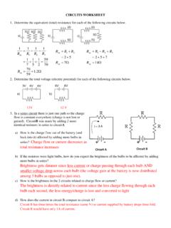
9 The power rating of a resistor corresponds to the maximum power that the device can dissipate without adversely affecting its operation. When the power rating is exceeded the resistor overheats and it is destroyed by burning up. The power rating constraint is represented in the space by the thick curve shown on Figure 7. /iv Figure 7. Resistor characteristic curve with power rating constraint Spring 2006. Chaniotakis and Cory 6 Circuits and Networks By convention everything in a circuit is assumed to happen in the elements of a circuit , the lines just show the interconnections. Figure 8 represents a general circuit composed of elements e1 .. e5. The elements could be any two terminal devices (voltage source, current source, resistor, capacitor, inductor, etc). e1e5e4e2e3n1n2n3n4l1l2l3 Figure 8. Example Resistive network The terminals of the various elements are connected together forming the nodes n1 .. n4 as indicated on Figure 8. The connection between two elements is called a branch and the loops l1, l2 and l3 are closed connections of branches.
10 Spring 2006. Chaniotakis and Cory 7 Kirchhoff s Laws Kirchhoff s laws known as Kirchhoff s Current Law (KCL) and Kirchhoff s Voltage Law (KVL) are based respectively on the conservation of charge and the conservation of energy and are derived from Maxwell s equations. They along with Ohm s law present the fundamental tools for circuit analysis. Kirchhoff s Current Law states that: The current flowing out of any node in a circuit must be equal to the current flowing into the node. It is expressed mathematically as 10 Nnni== ( ) where N is the number of branches that are connected to the node. Consider the node shown on Figure 9. By adopting the sign convention that current flowing ito a node is positive (+) and current flowing out of the node is negative (-), application of KCL gives 1234iiii+=+ ( ) i1i3i2i4node Figure 9.