Transcription of REV SPEED METER Specific Wiring Diagram - A'PEXi
1 REV/ SPEED METER . Vehicle Specific Wiring Diagram This Wiring Diagram booklet is designed for use with the REV SPEED METER 405-A912/405-A916. Please be sure to read the instruction manual for the REV SPEED METER before performing installation. The REV SPEED METER requires both the Instruction Manual and the Wiring Diagram for proper Even though a vehicle is listed in this manual, there is a possibility that the unit will not operate properly due to modifications on the vehicle, special model differences, model changes, or other factors. This manual is accurate up until Mar. 2008. Please contact an Apex dealer for newer applications. 1. Table of Contents To begin 4. Installation Precautions 5. ECU Location Diagram 6. How to View the ECU diagrams 7. Installation Diagram Selection Tak 8. Connection Diagram (1)(2) 10.
2 Connection Diagram (3)(4) 11. Connection Diagram (5)(6) 12. TOYOTA. Application Chart 13. ECU Diagram 20. NISSAN. Application Chart 24. ECU Diagram 28. HONDA. Application Chart 30. ECU Diagram 33. MITSUBISHI. Application Chart 35. ECU Diagram 37. MAZDA. Application Chart 38. ECU Diagram 40. SUBARU. Application Chart 42. ECU Diagram 44. SUZUKI. Application Chart 46. ECU Diagram 47. ISUZU. Application Chart 48. ECU Diagram 49. Manual Information Contact Information 2. To Begin Please read the safety precautions in the Instruction Manual before proceeding with installation. Glossary of Safety Terms are outlined in the Instruction Manual In this manual, the Electronic Control Unit is called the ECU. Caution Installation of this unit should ONLY be performed by a trained professional. Please hand this Wiring Manual and Instruction Manual to the Installer.
3 Never pull hard on any vehicle or product harnesses. Failure to do so may lead to electrical shorts and faulty connections. Be sure that all connectors have been securely locked into place. Also, be sure to loosen any bolts that secure the connector when removing. Failure to do so may cause damage to the connector. Keep the vehicle and product harnesses away from high temperatures and moving parts. Also, keep the harness away from water. Failure to do so may result in electrical shorts and faulty operation. Keep all harnesses away from sharp objects. Do not put excessive strain on the harness. Failure to do so may lead to electrical shorts. 3. Installation Precautions Do not use electro taps in the installation of this product. Electro taps can become loose over time causing the unit to malfunction.
4 This can also lead to vehicle and product damage. Be sure to use wire crimpers and the included splices for a secure connection. Be sure that the harness is not exposed to metal. Always wrap all connections with electrical tape. How to use the Fittings Strip 5mm from wire Insert sleeve over wire Bend back exposed wire Place male fitting over exposed wire * Use Diagram below to ensure proper connection Clamp the wire here Tighten the fitting as shown Clamp the wire cover here How to use the Splices Remove 5mm of the Strip 10mm from Wrap the two Securely fasten together wire cover from the other wires together other connection wire the connecting wire connection wire * be sure to cover the connection with electrical tape 4. ECU Arrangement Diagram Perform installation by referring to the symbols in the corresponding columns of the tables of applicable models on and after page 10.
5 A : Lower part of the passenger seat dash side B : Right side of the glove box C : Foot position of the passenger seat D : Inner part of the glove box E : Inner part of the center console F : Under the driver's seat G : Under the passenger seat H : Near the steering column I : Left side of the METER panel J : Lower part of the driver's seat dash side K : Left side of the center console L : Engine room M : Before the rear trunk N : Behind after the driver's seat O : Behind the passenger seat P : Upper inner part of the center console 5. How to Refer to the ECU Terminal Arrangement Diagram This ECU terminal arrangement Diagram is viewed from the direction of the arrow. The direction of the ECU varies depending upon the vehicle. Perform the installation work after confirming the connector shape and the number of pins.
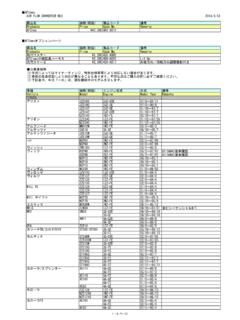
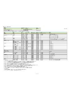
6 Warning If any abnormal noise or abnormal smell is sensed during the installation work of this product, stop the work immediately and contact the distributor or your nearest A PEX business office Continuing the installation under such conditions may cause an electric shock or fire causing damage to electric devices. 6. Installation Diagram Selection Table Vehicles not listed below will use Connection Diagram (1) or (2). SPEED Limiter Note Name Type Engine Year CUT RETAIN. s .. 3 .. Torneo .. 4 .. Accord .. 4 .. Accord Wagon .. 4 .. Odyssey 4 .. Fit 4 .. Fit Aria 4 .. When connecting the IG Power, Engine RPM, Ground, Vehicle SPEED signal wires to the ECU, be sure to check the Connection Diagram (1)-(4) for proper connection. Also check P16 for vehicle Specific information. 7. Connection Diagram (1) When NOT Cutting SPEED Limiter IG Power RPM.
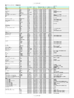
7 Ground SPEED . Red: IG Power Yellow: RPM. Black: Ground Purple: SPEED 1 Input Connection Diagram (2) When Cutting SPEED Limiter IG Power RPM. Ground . SPEED Red: IG Power Yellow: RPM. Black: Ground Pink: SPEED 1 Output Purple: SPEED 1 Input 8. Connection Diagram (3). IG Power RPM. Ground SPEED . Red: IG Power Yellow: RPM. Black: Ground Brown: SPEED 2 Output Purple: SPEED 1 Input Connection Diagram (4). IG Power RPM. Ground SPEED . METER Signal Open Red: IG Power Yellow: RPM. Black: Ground Brown: SPEED 2 Output Purple: SPEED 1 Input Pink: SPEED 1 Output 9. Application Chart (TOYOTA). Name Type Engine Year ECU Notes Diagram .. Soarer .. Mark II/. Chaser/. Cresta .. 5: JZX 100 : For Mark ,incompatible up to model year 10. Name Type Engine Year ECU Notes Diagram .. Supra .. Turbo A.. Altezza.
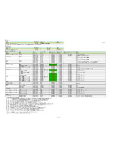
8 MR-S .. Includes Sequential .. MR2 .. Celica .. 11. Name Type Engine Year ECU Notes Diagram .. c . Curren .. A/T w/ TRC. A/T w/o TRC . w/TRC .. w/o TRC .. c . Carina ED . Corona EXIV .. A/T w/ TRC. A/T w/o TRC . w/ TRC .. w/o TRC .. d c 2WD w/ TRC . Caldina . 2WD w/o TRC .. 12. Name Type Engine Year ECU Notes Diagram .. Corolla FX .. Corolla .. Sprinter .. Corolla Levin .. Sprinter Trueno .. Corolla Celes .. Sprinter Marino .. Starlet .. 13. Name Type Engine Year ECU Notes Diagram b .. c .. Vitz .. Not Including .. Fun Cargo models installed with Steermatic .. Estima .. c Mark II Qualis .. d 14. Name Type Engine Year ECU Notes Diagram .. Platz .. Corolla .. d .. Corolla .. Fielder d .. i .. 15. ECU Diagram (TOYOTA). T1-a T2-a 10p 18p 14p 10p 18p 24p RPM RPM SPEED Ground SPEED IG Power Ground IG Power T3-a T4-a 26p 16p 26p 16p 12p RPM RPM.
9 Ground SPEED IG Power Ground SPEED IG Power T4-b 26p 16p 12p T5-a 26p 16p 22p RPM SPEED SPEED IG Power IG Power Ground RPM Ground T5-b T5-c 26p 16p 22p 26p 16p 22p SPEED SPEED Ground IG Power RPM Ground RPM IG Power T5-d T6-a 26p 16p 22p 26p 16p 12p 22p RPM SPEED SPEED Ground IG Power Ground RPM IG Power 16. T6-b T7-a 26p 16p 12p 22p RPM SPEED SPEED Ground IG Power Ground RPM IG Power T8-a T8-b 34p 22p 16p 28p 34p 22p 16p 28p RPM SPEED RPM SPEED Ground IG Power Ground IG Power T8-c 34p 22p 16p 28p T8-d 34p 22p 16p 28p RPM SPEED RPM SPEED Ground IG Power IG Power Ground T9-a 31p 24p 28p 22p Ground IG Power RPM SPEED T9-b 31p 24p 28p 22p SPEED Ground RPM IG Power 17. T10-a 31p 24p 17p 28p 22p RPM Ground SPEED IG Power T10-b 31p 24p 17p 28p 22p Ground SPEED IG Power RPM. T10-c 31p 24p 17p 28p 22p RPM Ground SPEED IG Power T10-d 31p 24p 17p 28p 22p Ground RPM SPEED IG Power T11-a 34p 35p 35p 31p Ground RPM.
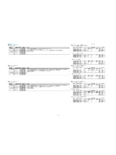
10 IG Power SPEED 18. Application Chart (NISSAN). Name Type Engine Year ECU Notes Diagram President .. Infiniti Q45 .. Cima .. Cima .. Cima .. Fairlady Z .. Leopard .. Leopard J Feri .. Cedric/Gloria .. Excluding .. 5AT cars .. Cefiro Wagon .. Terrano .. 19. Name Type Engine Year ECU Notes Diagram .. Cefiro .. Excluding 5AT cars .. Laurel .. Excluding . 5AT cars .. Excluding 5AT cars Skyline .. Excluding 5AT cars .. Stagea .. Stagea Autech .. 20. Name Type Engine Year ECU Notes Diagram .. Blue Bird .. Sylphy .. Blue Bird .. Silvia .. 180SX .. Not Including N1.. Pulsar .. Primera Wagon .. 21. Name Type Engine Year ECU Notes Diagram .. Primera .. Wing Road .. Avenir .. Sunny .. NX Coupe .. Including .. CGA3DE . March .. Including . Cube CGA3DE. 22. ECU Diagram (NISSAN). N1-a N2-a 16p 12p 20p 16p 15p 12p 20p 16p Ground RPM Ground RPM.