Transcription of Review of Circuits as LTI Systems - Ted Pavlic
1 ECE 209: Circuits and Electronics LaboratoryReview of Circuits as LTI Systems Math Background: ODE s, LTI Systems , and Laplace TransformsEngineers must have analytical machinery to understand how Systems change over time. For example,springs and dampers in car suspension Systems absorb kinetic energy after road disturbances and dissipatethe energygentlyover time. Electronic filters protect Circuits from large input transients in a similar , engineers need to know how to choose components Systems and ODEs:The motion of many physical Systems can be modeled knowing only a fewof its derivatives. For example, a car s position over time can be described well knowing its velocity oracceleration. So we focus on thelinear time-invariant(LTI) systemx(t)LTI Systemy(t)which has inputx(t) ( , height of terrain under the car) and outputy(t) ( , height of passenger s seat).By our assumption that all we need are a few derivatives of the inputand the output, then a typicalordinarydifferential equation(ODE) that might model such a system isy + 3y + 2y=x x(1)wherey andy are the first and second derivatives of signaly(t).
2 Given a known inputx(t), we would liketointegratethis differential equation to find an expression ofy(t) that is only in terms oft. Then we can seehow to adjust our design parameters so thaty(t) has a desirable shape ( , even with a bumpyx(t) roadsurface, the car seaty(t) stays in one place). So we need a convenient way tosolvethis differential Decomposition:Assume thatxcan be broken into two parts so thatx(t) =x1(t) +x2(t). Byinspection, if I can solveEquation (1)for the responsey1tox1alone and the responsey2tox2alone, thenthe responseytoxwould bey1+y2. Further, imagine that I could find a set of functions such that: When a function in the set is an input toEquation (1), the output is simple to find. Every useful inputx(t) can be expressed as a sum (or integral) of functions from this this case, solving ODE s likeEquation (1)would be trivial. Before even knowing the inputx, I could findthe solution to the ODE for every function in this special set.
3 Then when I finally do know my input, I justsum up the relevant prototypical acomplex exponentialfunctionf(t),Aestwheres, +j is acomplex numberwith real part and imaginary part , andAis also a complex number . Just as with a purely real exponential function,f (t) =sAest=sf(t) and f(t) dt=1sAest=1sf(t).(2)That is, for an exponential ( ,Aest), differentiation is identical to multiplication bysand integration isidentical to division bys. So complex exponentials turn ODE calculus ( , df /dtand fdt) into simplealgebra ( ,sfandf /s). Moreover, this property holds whensis purely real or and the Characteristic Response:Because everyx(t) =x(t) + 0, then the zero-input caseis important to us, and we should handle it first. These zero-input effects will be a part of every solutionregardless of the input, and so the output trajectory for zero input is called thecharacteristicorintrinsicortransientr esponse of the system .
4 We will assume that this output is made up of complex exponentials,and so we lety(t),Aestandx(t),0, which turnsEquation (1)intoAest(s2+ 3s+ 2)= 0,(3)and so we must solve for values ofsthat make this equation true. Fortunately,|Aest| 6= 0 for alls, and sothe roots of thecharacteristic polynomials2+ 3s+ 2,s= 1ands= 2,(4) Document Source code 2007 2011 by Theodore P. PavlicCreative Commons Attribution-Noncommercial LicensePage 1 of 4 ECE 209 Review of Circuits as LTI Systemsboth solveEquation (3). Hence, thezero-input transient responseofEquation (1)isy0(t) =Ae 1t+Be 2twhereAandBare complex numbers that correspond to different initial conditions. Becausee t 0 ast for all <0, theny0(t) 0 ast . So as long as the roots inEquation (4)are very negative,theny0(t) will decayquickly, and we can usuallyignore its general, the roots of the characteristicpolynomial are calledeigenvalues( , intrinsic values or characteristic values ).
5 When therealpartof the eigenvalues arenegative, then the characteristic response will continuously decay. Such LTI systemsare calledSTABLE because aspects of the output that are not due to the input will always decay to have components that grow and eventually dominate the Response to an Input:Now we assume that the LTI system isstable( , its eigenvalues havenegative real parts) so that we can focus on the system after itstransient response has decayed out. So weconsider the inputx(t),XestwhereXis some complex number . It seems reasonable to guess that theoutputy(t) =Y estwhereYis some complex number . If our guess is wrong, there will be no solution, andwe will try something else. So under these assumptions,Equation (1)becomesY est(s2+ 3s+ 2) =Xest(s2 1).Again because|est|6= 0 for alls,YX=s2 1s2+ 3s+ 2.(5)That is, for a given inputXest, we can find the outputY estby scalingXby the ratio inEquation (5).
6 Thistransfer functionrepresents the impact of the system on any individual complex exponential. Thedenominator of the transfer function is the characteristic polynomial of the system . The system s eigenvaluesare calledpolesbecause the transfer function s denominator iszerothere, and so the transfer function smagnitude is like a tent being pulled toward the sky by each of its poles. So given a transfer function, wemust make sure its denominator roots ( , poles) have negative real example, ifx(t),e 2tcos(3t), then the input can easily be expressed as a sum of complex exponen-tials usingEuler s formula. That is,x(t) =e 2tcos(3t) =e 2tej3t+e j3t2=12e( 2+j3)t+12e( 2 j3)t,which is a kind of generalized Fourier series of the signal. So the response tox(t) is the sum of (1/2)e( 2+j3)tand (1/2)e( 2 j3)tscaled by the transfer function evaluated ats= ( 2 +j3) ands= ( 2 j3).Laplace Transforms and the Frequency Domain:All that is left is representing any inputxas a sumor integral of complex exponentials.
7 Ifxcanbe expressed this way, then mathematical theory statesx(t) =12 j +j j X(s)estdswhereX(s) = 0 x(t)e stdt.(6)That is, theLaplace transformX(s) of signalxprovides the coefficient for theestpart of the signal, and wecan scaleX(s) by the transfer function to find how much ofestcontributes to our output. Luckily,(i) Most inputs interesting to engineersdohave Laplace transforms.(ii) Many common signals have well-documented Laplace transforms.(iii) Operations on Laplace transforms form other Laplace transforms. For example, the signalg(t) +h(t)has the Laplace transformG(s) +H(s). More importantly, the signal dg(t)/dttransforms tosG(s).(iv) As long as each of thepolesof arealsystem s transfer function has a negative real part, the inputX(s) and transfer function only need to be evaluated ats=j for all > ofitem (iv), design work onfiltersfocuses on thefrequency (orFourier) spectrum. That is, wethink of the frequency content ( , fast changing or slow changing ) of inputs and the ability of systemsto shape that content ( , slows the signal or removes slow changes ).
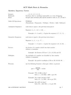
8 Because ofEuler s formula, wecan think of sinusoids with angular frequency rather thanej tcomplex exponentials. Transfer functionsthen have again magnitude( , from dissipative attenuation) andphase shift( , from delay) for each .Copyright 2007 2011 by Theodore P. PavlicCreative Commons Attribution-Noncommercial LicensePage 2 of 4 ECE 209 Review of Circuits as LTI SystemsLaplace Representations of circuit ElementsResistors, capacitors, and inductors are important tools in electronic design. The following summary assumeszero initial +vC CiC(t) =Cv C(t)IC(s) =sCVC(s)ZC(s),VC(s)IC(s)=1sCiL+vL LvL(t) =Li L(t)VL(s) =sLIL(s)ZL(s),VL(s)IL(s)=sLiR+vR RvR(t) =RiR(t)VR(s) =RIR(s)ZR(s),VR(s)IR(s)=RThe Laplace transformations of the voltage-to-current equations use the fact that derivatives in thetimedomaincorrespond to multiplication bysin theLaplace domain. Theimpedanceof a circuit element is itsvoltage-to-current ratioat a given example, assume that the voltage driving a capacitor isvC,sin(2t).
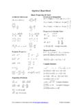
9 Then the currentiC=Cv = 2 Ccos(2t). Hence, max{vC}/max{iC}= 1/(2C) which matches|ZC(j2)|=|1/(j2C)|= 1/(2C). The larger the capacitance, the larger the current, and so bigger capacitorsprovideless impedanceto high frequency ImpedanceReducing a complicated network of impedances to a few equivalent impedances is a common circuit analysistask. Consider the equivalent impedance ofnimpedances in series. Apply the (Laplace-domain) loop VoutVin=ZseriesIVoutVinThe equivalent impedanceZseriesis the total voltage drop divided by the series current. That is,Zseries(s)=Vin(s) Vout(s)I(s)=I(s)Z1(s) +I(s)Z2(s) + +I(s)Zn(s)I(s)=Z1(s) +Z2(s) + +Zn(s),and so theequivalent series impedanceis thesimple sum of the constituent ImpedanceNext, consider the equivalent impedance ofnimpedances in parallel, which is often denotedZ1kZ2k equivalent impedanceZparallelis the voltage drop divided by the total current. That is,Zpar(s)=Vin(s) Vout(s)Vin(s) Vout(s)Z1(s)+Vin(s) Vout(s)Z2(s)+ +Vin(s) Vout(s)Zn(s)=(1Z1(s)+1Z2(s)+ +1Zn(s)) thespecial butvery commoncaseof onlytwobranches ( ,n= 2),Z1k2(s),Z1(s)kZ2(s) =(1Z1(s)+1Z2(s)) 1=(Z2(s) +Z1(s)Z1(s)Z2(s)) 1=Z1(s)Z2(s)Z1(s) +Z2(s).
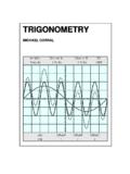
10 Copyright 2007 2011 by Theodore P. PavlicCreative Commons Attribution-Noncommercial LicensePage 3 of 4 ECE 209 Review of Circuits as LTI SystemsThe Voltage DividerMost passive electronic Circuits can be reduced to avoltage dividerwhich splits a driving signal between VZAIZBIVinVoutThe (Laplace-domain) current through the entire circuit isI(s) =Vin(s)ZA(s) +ZB(s),and the outputVout(s) =I(s) ZB(s), andVout(s)Vin(s)=ZB(s)ZA(s) +ZB(s).So at each frequency , the output is the same proportion of the input asZBis of the totalZA+ , the value of impedancesZAandZBvary with : AnRCLow-Pass Filter0 VRCVinVoutVout(s)Vin(s)=1sCR+1sC=1sRC+ 1 The DC ( , constant) parts ofVinare passeddirectly through the filter and show up at the components of the input inducedisplacement currentwithin the capacitor, and so they getattenuatedthroughthe resistor. SoVoutis a slower version Filters: Shortcut via Th evenin Equivalent SourceWhen anRCcircuit containsonlyonecapacitorand an outputacross that capacitor,it s helpful to convertthe rest of the circuit into itsTh evenin equivalent; the result is a simple voltage divider.