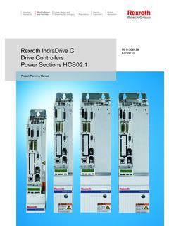
Transcription of Rexroth IndraDrive C - Converting Systems Inc.
1 Rexroth IndraDrive CDrive , 01 Operating InstructionsElectric Drivesand Controls PneumaticsServiceLinear Motion and Assembly TechnologiesHydraulicsAbout this DocumentationRexroth IndraDriveDOK-INDRV*-FU**-IB01-EN-PRexro th IndraDrive CDrive , InstructionsDOK-INDRV*-FU**-IB01-EN-PDoc ument Number, 120-2400-B327-01/EN; Mat. No.: R911314905 This documentation describes the mounting, installation, commissioning,parameterization and troubleshooting of Rexroth IndraDrive controllers onthe basis of the power sections HCS02 or HCS03 and the control sectionsBASIC OPENLOOP or BASIC PROFIBUS with comfort control *-FU**-IB01-EN-P06-2006 First Release Bosch Rexroth AG 2006 Copying this document, giving it to others and the use or communicationof the contents thereof without express authority, are forbidden. Offendersare liable for the payment of damages. All rights are reserved in the eventof the grant of a patent or the registration of a utility model or design(DIN 34-1).
2 The data specified above only serve to describe the product. Nostatements concerning a certain condition or suitability for a certainapplication can be derived from our information. The given informationdoes not release the user from the obligation of own judgement andverification. It must be remembered that our products are subject to anatural process of wear and Rexroth 2 D-97816 Lohr a. MainTelephone +49 (0)93 52/40-0 Tx 68 94 21 Fax +49 (0)93 52/40-48 85 EDY1 (RR/US/BB)This document has been printed on chlorine-free bleached of DocumentationDocument TypecodeInternal File ReferencePurpose of DocumentationRecord of RevisionsCopyrightValidityPublished byNoteRexroth IndraDriveContents IDOK-INDRV*-FU**-IB01-EN-PContents1 Introducing the .. 1-1 Terms, Basic Principles .. IndraDrive Hardware Platform ..1-6 drive Controllers .. 1-6 Motors and Measuring Systems .. 1-7 Master IndraDrive Firmware Platform.
3 1-8 Type Code .. 1-8 Functions Overview .. IndraDyn 1-12 Housing 1-12 Kit Motors at IndraDrive 1-13 General Information on Third-Party Motors .. 1-13 Requirements on Third-Party Motors .. 1-14 Requirements on the Encoder of the Third-Party Motor .. 1-17 Notes on Selection and , Listing .. 1-182 Important Directions for Use .. 2-1 Introduction .. 2-1 Areas of Use and Application .. Use .. 2-23 Safety Instructions for electric Drives and Information .. 3-1 Using the Safety Instructions and Passing them on to Others .. 3-1 Instructions for 3-1 Explanation of Warning Symbols and Degrees of Hazard Seriousness .. 3-3 Hazards by Improper with Regard to Specific 3-5 Protection Against Contact with Electrical Parts .. 3-5 Protection Against electric Shock by Protective Low Voltage (PELV) .. 3-6 Protection Against Dangerous Movements .. 3-7II ContentsRexroth IndraDriveDOK-INDRV*-FU**-IB01-EN-PProte ction Against Magnetic and Electromagnetic Fields During Operation andMounting.
4 3-9 Protection Against Contact with Hot Parts .. 3-10 Protection During Handling and 3-11 Battery Safety .. 3-11 Protection Against Pressurized Systems .. 3-124 Identification, Transport, Storage, Installation 4-1 Type Code .. 4-1 Type and 4-6 Transport of the Devices .. 4-6 Storage of the Devices .. 4-7 Ambient and Operating 4-7 Compatibility with Foreign Matters .. 4-95 Electrical Sections .. 5-1 Type Current and Connected Load .. 5-1 Control Voltage 5-2 Power Voltage Supply- Mains Connection .. 5-3 Limited Length of Motor Power Cables .. Sections .. 5-6 Relay Contact Type 1 .. 5-6 Relay Contact Type 2 .. 5-6 Relay Contact Type 3 .. 5-7 Digital Inputs/Outputs .. 5-7 Analog Inputs/Outputs .. 5-15 Mains Filter 5-15 Mains Filter (-Combination) 5-16 Mains Choke (feeding).. 5-16 Mains Choke **-S (Current-Compensated) .. 5-17 Braking Resistor HLR ..5-17 Motor Filter 5-266 Mounting and .. 6-1 Dimensions Power 6-1 Dimensions Mains Filter 6-7 Dimensions Mains Choke (infeeding).
5 6-9 Dimensions Standard Braking Resistors 6-12 Dimensions Reinforced Braking Resistors 6-14 Dimensions Motor Filter 6-17 Combination of drive Controllers of the Rexroth IndraDrive C Product Range .. 6-22 Rexroth IndraDriveContents IIIDOK-INDRV*-FU**-IB01-EN-PMultiple-Lin e Arrangement of drive Controllers .. Installation .. 6-25 Rules for Design of Installations with drive Controllers in Compliance with EMC .. 6-25 EMC-Optimal Installation in Facility and Control 6-26 Ground Signal Lines and 6-33 General Measures of Radio Interference Suppression for Relays, Contactors,Switches, Chokes, Inductive 6-34 Installing the 24V Supply ..6-35 Connection Diagram ..6-36 Connections and Connectors .. 6-38 Accessories HAS .. 6-677 Commissioning and .. 7-1 Control Panels .. 7-1 Parameters .. 7-1 Master Communication 7-3 Parameterization Mode / Operating Mode .. 7-4 Default Settings in the Motor Encoder Data Memory ("Load Defaults Procedure") .. 7-12 Control Panels.
6 7-12 Menu Structure .. of Parameters Base 7-36S-0-0000 S-0-0100 ..7-36S-0-0101 S-0-0200 ..7-41S-0-0201 S-0-0300 ..7-45S-0-0301 S-0-0400 ..7-47S-0-0401 S-0-1000 ..7-50P-0-0001 P-0-0689 (General Functions) .. 7-51P-0-0690 P-0-0899 (Synchronization Mode).. 7-85P-0-1100 P-0-1299 (Velocity Control) .. 7-87P-0-1500 P-0-1599 (General Device Parameters) .. 7-96P-0-2000 P-0-2999 (General Device Parameters .. 7-96P-0-3600 P-0-4095 (General Device Parameters) .. Functions .. 7-108 Serial Communication .. 7-108 Master 7-110 Profile 7-114 Motor Control .. 7-117 Scaling of Physical Data .. Operation (Open-Loop U/f Control) .. 7-121 Automatic Setting of Motor Control Axis Control (Closed-Loop Operation) .. 7-131 Automatic Setting of Axis Control .. Block Mode .. 7-137IV ContentsRexroth IndraDriveDOK-INDRV*-FU**-IB01-EN-P8 Diagnostic and Service System .. 8-1 Diagnostic Status Messages .. 8-1 Diagnostic Command 8-1 General Description of Error Messages and Error Reactions.)
7 Actions for Operating States, Activities and Reactions of the DriveController .. 8-21 Check drive 8-21 Replacing Devices .. 8-23 Replacing the Release Update .. 8-25 Firmware Version 8-29 Possible Problems during Firmware Replacement .. and Maintenance .. 8-36 Deactivation .. 8-36 Dismantling .. 8-36 Disposal .. 8-37 Environmental Protection .. 8-379 Service & .. der - Before contacting .. - Sales & Service 9-210 Index10-1 Rexroth IndraDriveIntroducing the Products 1-1 DOK-INDRV*-FU**-IB01-EN-P 1 Introducing the IntroductionTerms, Basic PrinciplesParametersCommunication between master and drive takes place, with a fewexceptions, by means of are used for: determining the configuration parameterizing the control loop triggering and controlling drive functions and commands transmitting command values and actual values (according torequirements, cyclically or acyclically)All operating data are mapped to parameters!
8 The operating data stored in parameters can be identified by means ofthe IDN. They can be read and transferred, if required. The user writeaccess to parameters depends on the properties of the respectiveparameter and the current communication phase. Specific parametervalues (operating data) are checked for validity by the drive Storage and Parameter HandlingSeveral non-volatile data memories are available in an IndraDrive device: in the controller in the motor encoder (depending on motor type)In addition, a volatile data memory (working memory) is available in as supplied of the Rexroth drive components: The controller memory contains the drive firmware and the controller-specific parameter values. The motor encoder memory contains the encoder-specific and,depending on the motor type, the motor-specific parameter application-specific parameter values are stored in the controller.
9 Dueto the limited number of writing cycles of non-volatile storage media,application-specific parameter values can be stored in the workingmemory (volatile memory), application-specific parameter values is required in the followingcases: after initial commissioning of the machine axis or the motor before replacing the controller for servicing (if possible)Application-specific parameter values can be saved via: "IndraWorks D" commissioning tool saving the parameter values onexternal data carrier control master saving the parameter values on master-side datacarrier comfort control panelData MemoryCondition As SuppliedStoring the Application-SpecificParameter ValuesSaving Parameter Values1-2 Introducing the ProductsRexroth IndraDrive DOK-INDRV*-FU**-IB01-EN-PThe drive supports master-side saving of parameter values by listingparameter identification numbers (IDNs). Using these lists guaranteescomplete storage of the application-specific parameter values.
10 It is alsopossible to determine IDN lists defined by the parameter values is required in the following cases: initial commissioning of the motor (loading basic parameter values andmotor-specific parameter values) serial commissioning of machine axes at series machines (loading thevalues saved after initial commissioning) reestablishing a defined original status (repeated loading of the valuessaved after initial commissioning) replacing the controller for servicing (loading the current parametervalues saved before servicing) Possibilities of loading parameter values to the controller: motor encoder data memory loading the parameter values bycommand or via the control panel during initial motor commissioning "IndraWorks D" commissioning tool loading the parameter valuesfrom external data carrier control master loading the parameter values from master-side datacarrierBy means of checksum comparison, the control master can determinewhether the values of the application-specific parameter values currentlyactive in the drive correspond to the values saved on the master controllers provide the possibility to protect parameter valuesagainst accidental or unauthorized change by means of a password.