Transcription of RF/Microwave Circuits I - Baylor ECS
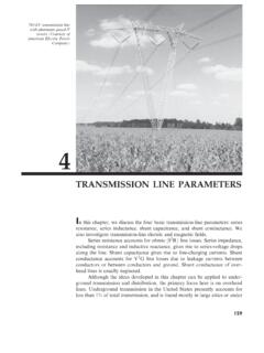
1 1RF/ microwave Circuits IBalunsFall 2007 Baluns A balun (balanced-to-unbalanced) is a transformer used to connect balanced transmission line Circuits to unbalanced ones Two conductors having equal and opposite potential constitute a balanced line Microstrip and coaxial cables use conductors of different dimensions these are unbalanced +-Ground shieldThis shielded 2-wire line is balanced no current will flow through the shield 2 Baluns There are many different types of baluns the different designs that have been developed generally depend on The bandwidth required The operating frequency The physical architecture of the network (what types of components are being connected and in what configuration) In some cases active baluns (using transistors) are used but these are typically only found in integrated circuitsInner ConductorsShieldingIoI2I1 Front ViewSide ViewI3I1= I2, I3=0 Baluns When do you need a balun?
2 Balanced mixers Push-pull amplifiers Balanced frequency multipliers Phase shifters Balanced modulators Dipole antenna feeds Whenever a circuit design requires signals on two lines that are equal in magnitude and 180 degrees out of phaseMicrostrip feed line Dipole antennaIf you just connect one arm of the dipole to ground the antenna does not work properly! 3 Baluns - ExampleLow Profile BalunTwo wires feed linesDipole AntennaCoax ConnectorBalun - Example Schematic of the balun from the previous 1 CLIN 2 TLIN 1 TLIN 4 TLIN 3 TLIN 7 Term 1Z = 50 OhmsTerm 2Z = 28 OhmsTerm 3Z = 28 OhmsCoax Connector PortDipole Antenna Port(s) 4 Balun Other ExamplesLange CouplerMarchandSurface Mount Baluns The basics a transformer is two windings linked by a magnetic field As current passes through the primary coil and creates magnetic flux, a current in the secondary coil arises to generate an opposing field this you know from basic EM theory, right-hand rule, etc.
3 An implication of this fact is that a polarity difference exists between terminals on either side of the transformer Many times you cannot SEE how the coils are wound, so you need to rely on how the vendor has marked the package In-phase terminals are usually marked with a dot 5 Surface Mount Baluns Important terms: Amplitude balance how closely matched are the amplitudes of the two output signals Phase balance how well does the phase of one output track the phase of the second output Insertion loss (we know this one)groundinputOutput 1 Output 2(ground)Surface Mount Baluns Baluns are commonly made using the center-tapped transformer below Each output is terminated by N2Z1/2 The center tap (nodes 4,5) is grounded This provides a 180-degree phase difference between nodes 3 and 6(+)(gnd)(-) 6 Surface Mount Baluns Typical equivalent circuit with parasitic elements (these should look somewhat )Surface Mount Baluns Do we need anything other than surface mount baluns?
4 Answer = of course, sometimes Non-planar components may not be ideal Frequency range may be limited Integrated designs are sometime required Configuration may not work in architecture for other reasons 7 Distributed Balun Designs A simple example is a transition between a microstrip line (unbalanced) and a stripline (balanced) A stripline is similar to microstrip, except both conductors have the same dimension Various techniques for tapering the dimensions of the lower conductor have been developedMicrostripStriplineGroundSignal Taper sectionLower conductor continues underneathDistributed Balun Designs Coupled microstrip lines can also be used to realize a balun:3241If a short circuit is placed at port 2:S11is zero if Zo,odd= Zo/ 2()()evenoddevenoddYYYYSS,0,0,0,04131+ =We want this ratio to be -1 over a wide bandwidth, which requires =evenZ,0 Analyze at fc, when the length = /4 8 Distributed Balun Designs Achieving a high even-mode impedance(when both strips are at the same potential)
5 Means the ground plane has little effect Thick, low dielectric constant substrates Very thin conductors Achieving this in practice can be difficult, so this type of balun is not always the best solution3241 Distributed Balun Designs Planar Transmission Line Baluns consist of two sections The first section divides the signal into two signals with equal amplitude and phase The second section provides -90 degrees and +90 degrees phase shift for the signals, so the total phase difference between outputs is 180 degrees A Wilkinson divider is often used for the first section; multi-section Wilkinson dividers can provide very wide bandwidthTermTerm1Z=50 OhmNum=1 TermTerm3Z=50 OhmNum=3 TermTerm2Z=50 OhmNum=2 CLINTL3E=90RR1R=100 OhmTLINTL4E=90 CLINTL5E=90 TLINTL1E=90 WilkinsonCoupled line sections(Lange couplers often used) 9 Distributed Balun DesignsTermTerm2Z=50 OhmNum=2 TermTerm1Z=50 OhmNum=1 CLINTL6E=90 TermTerm2Z=50 OhmNum=2 TermTerm1Z=50 OhmNum=1 CLINTL6E=90[] =00jjSopen[] =00jjSshort180 degree phase differenc