Transcription of RF Receiver INSTALLATION AND SETUP GUIDE
1 N7635-3V4 11/08 Rev. BADEMCO 5881EN SeriesRF ReceiverINSTALLATION AND SETUP GUIDE INTRODUCTION The 5881EN Series of RF receivers is designed for use with control panels that support an RF Receiver connection via the keypad terminals. The Receiver recognizes alarm, status, and keypad control messages from wireless transmitters operating at 345 MHz. One or two individually identified receivers can be employed, depending on the control used. Connection of multiple receivers to a control can provide redundant coverage or extend coverage in large areas. These receivers feature a Spatial Diversity System that virtually eliminates the possibility of "nulls" and "dead spots" within the coverage area.
2 The 5881EN series of receivers use ADEMCO s High Security technology, and can be used in commercial fire installations. Additionally, the 5881 ENHC Receiver contains front and back tamper that permits its use in commercial burglary and fire installations. UL For 5881 ENHC Receivers: In commercial fire applications, the Receiver can only be used with control panels that are approved for use inCommercial Fire Installations. When the 5881 ENHC is used in commercial fire applications, DIP switch 5 mustbe in the ON position. In commercial burglary applications, the 5881 ENHC canonly be used with control panels that are approved foruse in Commercial Burglary Installations.
3 In commercial fire applications, a keypad must beconnected to Keypad Port 2 in the control. The keypadmust be mounted on the control or within 3 feet of thecontrol with the wiring encased in conduit. All power-limited wiring must be separated from non-power limited and high-voltage wiring by " ( ). Each Receiver supports the number of zones shown below. 5881 ENL Up to 8 zones 5881 ENM Up to 16 zones 5881 ENH *See below 5881 ENHC *See below * The number of zones that the 5881 ENH Receiver can support depends on the control with which it is used. See the control panel s instructions for specific details. If a Receiver is connected to a system in which more than the permitted number of wireless zones have been programmed, a "SET UP ERROR" message (on alpha keypads) or an "E4 or E8 " message (on fixed-word keypads) will be displayed on the system's keypad, and none of the zones will be protected.
4 The instruction manual that accompanies the control includes recommendations regarding Receiver and transmitter locations, the types of wireless zones that can be programmed ( , ENTRY/EXIT, PERIMETER, INTERIOR, etc.) and the procedure for programming the receivers. These receivers should not be installed in an area subject to environmental extremes of below freezing (such as an unheated warehouse) or extremely high temperatures (such as an attic). INSTALLATION With some controls, a Receiver may be mounted directly inside the control's cabinet ( Receiver circuit board only, without its plastic housing) instead of remotely (in its own housing).
5 In both cases, avoid mounting the Receiver antennas against a metal surface. NOTE: You may only mount the 5881 ENHC its own plastic housing. If you attempt to mount the 5881 ENHC in the control s cabinet, the Receiver constantly reports a tamper condition. 1. Remove the Receiver 's cover by inserting a screwdriver blade in the slot at the center of the cover's lower edge. 2. If the Receiver is to be mounted within the control's cabinet (refer to Figure 1): a. Remove the Receiver 's circuit board from its base by bending back the two flexible plastic tabs that hold the board's lower edge. b. In the control's cabinet, unfasten and move the control circuit board downward (if already installed).
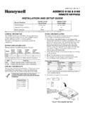
6 C. Hang two mounting clips (provided with the Receiver ) on the raised cabinet tabs, as shown in Detail B of Figure 1. d. Insert the top of the Receiver board between the rows of slots at the top of the cabinet, as shown in Detail A. e. Position the base of the Receiver board onto the mounting clips and secure to the cabinet with the supplied screws. See Detail B. f. Hang two mounting clips (supplied with the control board), on the raised cabinet tabs as shown in Detail C in Figure 1. g. Insert the top of the control board into the slots of the mounting clips secured in step e above. h. Position the lower end of the control board into place on the mounting clips and secure both to the cabinet with the two supplied screws.
7 I. Insert both grounding lugs (supplied with the Receiver ) through the top of the cabinet into the left-hand terminals of the antenna blocks (located on the upper edge of the Receiver board), and secure them to the cabinet with the screws provided, as shown in Detail D. j. Insert the Receiver s antennas through the top of the cabinet, into the blocks right-hand terminals, and tighten the screws. k. Affix the Receiver 's Summary of Connections label to the inside of the control's cabinet door. l. Discard the Receiver 's unused plastic cover and base. 3. If the Receiver is to be located remotely from the control in its own plastic enclosure (not in a cabinet): You will not need the circuit board mounting clips, grounding lugs and screws included with the Receiver .
8 A. If concealed wiring is to be used, route it through the rectangular opening at the rear of the base before mounting. For surface wiring entry, a thin breakaway area is provided along the base's right edge. b. Mount the Receiver in the selected location. For greatest security, use all four mounting holes (two key slot holes and two round holes) provided in the plastic base. c. If installing a 5881 ENHC, install a flat-head screw (supplied) in the case tamper tab as shown in Figure 2. When the Receiver is pried from the wall, the tamper tab will break off and remain on the wall. This will activate a tamper switch in the Receiver and cause generation of a tamper signal.
9 Note that this signal will also be generated when the Receiver s front cover is removed. d. Affix the Receiver 's Summary of Connections label to the inside of the housing cover. 2 MOUNTINGCLIPCABINETDETAIL DANTENNA AND GROUNDING LUG INSTALLATIONANTENNAMOUNT(2 PLACES)ANTENNA(2)SCREW(2)MOUNTINGCLIPCON TROLCIRCUITBOARDBOARDSUPPORTINGSLOTSHOLE S FOR ANTENNASAND GROUNDING LUGSRECEIVER CIRCUIT BOARD(See Detail D)++++RCVR BRDDETAIL ASIDE VIEWOF BOARD SUPPORTING SLOTSDETAIL BSIDE VIEWOF MOUNTINGCLIPDETAIL CSIDE VIEWOF MOUNTINGCLIPGROUNDINGLUG(2)pcb_RF_mount- V0 CIRCUIT BOARDCABINET Figure 1: Installing the Receiver Board in the Control s Cabinet 4. Setting the DIP switches (All Receivers): a.
10 Set the Receiver 's DIP switch (#2 through #4) to identify the Receiver 's address (refer to the DIP switch chart in the Summary of Connections Diagram on back cover). b. Verify that DIP switch #1 is in the OFF position. c. Set DIP switch #5 according to the following chart. DIP SWITCH #5 For .. Set to .. Commercial Fire Applications ON Non-commercial Fire Applications OFF NOTES: If multiple receivers are used on one control, DIP switch #5 must be set to the same position on all receivers. DIP switch #5 reduces sensitivity during supervision message reception. For commercial fire applications, DIP switch #5 must be in the ON position. 5. Insert the wiring plug (with 4 flying leads) into the mating socket on the Receiver (see Summary of Connections Diagram on back cover for socket location).