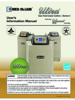
Transcription of RIELLO 40 SERIES - Weil-McLain
1 C6501000 F3-F5 I-O manual Rev4_3 1 RIELLO 40 SERIES MODELS 40 F3 & F5 EQUIPPED WITH ELECTRONIC AIR SHUTTER INSTALLATION & OPERATING MANUAL RESIDENTIAL OIL BURNERS NOTE: The settings in this manual are for retrofit applications. If this burner is being installed on a packaged unit (burner comes with the boiler or furnace), then follow the settings on the OEM page, as settings may differ. Burner is set for a single line system. C6501000 F3-F5 I-O manual Rev4_3 2 TABLE OF CONTENTS TECHNICAL DATA - Model TECHNICAL DATA Model OIL BURNER COMPONENT Serial Number INITIAL ASSEMBLY OF AIR TUBE TO BURNER MOUNTING BURNER TO BOILER OR Method 1-Universal Mounting Method 2-Semi-flange Method 3-Pedestal FACTORY APPLICATION FIELD NOZZLE INSERTION/REMOVAL OF DRAWER ELECTRODE TURBULATOR PUMP CONNECTIONS AND PORT Single Line (Gravity Feed)..12 Two Line (Lift System)..12 PUMP Single Line (Gravity System)..13 Two Line (Lift System).
2 14 SETTING THE AIR ADJUSTMENT BURNER ADJUSTMENT AMULET INSTALLATION SEQUENCE OF EXPLODED PARTS PARTS START UP INSTALLATION PACKAGE LIST Your RIELLO 40 burner should include the following parts. Please check to make sure all parts are present before beginning the installation. QTY. DESCRIPTION (parts bag) QTY. DESCRIPTION (carton) 2 - Mounting flange bolts (short) 1 - Burner chassis with cover 2 - Semi-flange bolts (long) 1 - Universal Mounting Flange 4 - Nuts 2 - Semi-flanges 2 - Chrome nuts 1 - Mounting gasket 1 - Oil pump connector (supply) 1 - Installation Manual 1 - Oil pump connector (return) 1- By-pass plug 1 - Female NPT adapter 1 - Male 3/8 NPT adapter * (Separate carton) 1 - mm Allen key 1 - Combustion Head * OEM burners shipped with combustion head mounted C6501000 F3-F5 I-O manual Rev4_3 3 BAEE1 FCD RIELLO 40 F3 TECHNICAL DATA DIMENSIONS MODEL F3 A B C D E F Inches 8 15/32 9 59/64 6 15/32 3 1/2 6 8 29/32 mm 215 252 164 89 152 226 E1: 10-inch long (254mm) tubes are also available.
3 SPECIFICATIONS FUEL: NO heavier than # 2 FUEL OIL FIRING RATE: to US GPH EFFECTIVE OUTPUT: 70,000 to 133,000 BTU/h VOLTAGE (Single Phase): 120V 60Hz (+ 10% - 15%) ABSORBED ELECTRICAL POWER: 155 Watts MOTOR (rated): 3250 rpm Run Current AMP CAPACITOR: Microfarads PUMP PRESSURE: 130 to 200 psig PRIMARY CONTROL: RIELLO 530 SE/C IGNITION TRANSFORMER: 8Kv 16mA MOUNTING FLANGE DIMENSIONS MODEL F3 A B C D Inch 1 1/4 1/4 7/16 2 3/16 mm 32 6 11 56 30 45 60 BC3 31/32" - 101mm5 1/2" - 140mm7 1/2" - 190mm8 15/32" - 215mmD7 3/32" - 180mmA C6501000 F3-F5 I-O manual Rev4_3 4 BAEE1 FCD RIELLO 40 F5 TECHNICAL DATA DIMENSIONS MODEL F5 A B C D E F Inches 9 11/64 10 11/16 7 3/32 3 1/2 6 9 13/32 mm 233 272 180 89 152 239 E1: 10-inch long (254mm) tubes are also available. SPECIFICATIONS FUEL: NO heavier than # 2 FUEL OIL FIRING RATE: to US GPH EFFECTIVE OUTPUT: 105,000 to 231,000 BTU/h VOLTAGE (Single Phase): 120V 60Hz (+ 10% - 15%) ABSORBED ELECTRICAL POWER: 175 Watts MOTOR (rated): 3250 rpm - AMP CAPACITOR: Microfarads PUMP PRESSURE: 130 to 200 psig PRIMARY CONTROL: RIELLO 530 SE/C IGNITION TRANSFORMER: 8Kv 16mA MOUNTING FLANGE DIMENSIONS MODEL F5 A B C D Inch 1 1/4 1/4 7/16 2 3/16 mm 32 6 11 56 30 45 60 BC3 31/32" - 101mm5 1/2" - 140mm7 1/2" - 190mm8 15/32" - 215mmD7 3/32" - 180mmA C6501000 F3-F5 I-O manual Rev4_3 5 OIL BURNER COMPONENTS IDENTIFICATION 12346571312119108 STANDARD RIELLO OIL BURNER MODELS 40 F3 & 40 F5 BURNER KEY COMPONENTS 1.
4 530 SE/C INTEGRATED PRIMARY CONTROL 7. ELECTRONIC AIR SHUTTER ASSY. 2. PRIMARY CONTROL SUB-BASE 8. WIRE HARNESS FOR AIR SHUTTER 3. FUEL UNIT (PUMP) 9. COMBUSTION HEAD WITH DRAWER ASSY. 4. PSC MOTOR 10. SEMI FLANGE 2 PIECES 5. CAPACITOR 11. UNIVERSAL MOUNTING FLANGE & GASKET 6. AIR ADJUSTMENT AND SHUTTER 12. AIR TUBE COVER PLATE 13 PUMP VALVE (COIL) *PLEASE READ THE MANUAL FOR SPECIFIC INFORMATION ON COMPONENTS **IF BURNER IS AN OEM BURNER KEY COMPONENTS MAY DIFFER SLIGHTLY BURNER SERIAL NUMBER IDENTIFICATION The RIELLO 15 character serial number, example, 99 A 8511111 00025, is identified as follows: 99 = last two digits of the year of manufacture; A = BI-week of manufacture; 8511111 = burner product code; 00025 = increment of 1 for each burner produced specific to product code reset to zero each January 1st. (99) (A) 8511111 00025 INITIAL SET-UP A) Remove burner and air tube from cartons. Check parts list (inside cover) to ensure all parts are present.
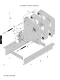
5 B) Remove burner cover by loosing the three screws securing it. Remove control box and air tube cover (see page 8). C) Remove drawer assembly from air tube, insert nozzle and set Turbulator adjustment for specific input required (see pages 8 & 9), then set aside. D) Mount air tube to burner chassis. (see next page) Year of manufacture BI-week of manufacture Burner product code Sequence C6501000 F3-F5 I-O manual Rev4_3 6 ASSEMBLY OF AIR TUBE TO BURNER CHASSIS The air tube and drawer assembly are shipped in a carton separate from the burner chassis. Choose the proper air tube length to obtain the tube insertion for the specific installation. A) Remove the AIR TUBE and BURNER CHASSIS from their respective cartons. B) Remove the DRAWER ASSEMBLY (1) from inside the AIR TUBE by loosening the screw (2). Carefully pull the DRAWER ASSEMBLY out of the AIR TUBE, install the required nozzle (see page 8) and set aside.
6 C) Remove the two BOLTS (3) from FRONT PLATE (4) of the BURNER CHASSIS. Align the two holes on the AIR TUBE HOLDING PATE (5) with the two holes on the BURNER CHASSIS FRONT PLATE with the BOLTS (3) removed. Replace the BOLTS and fingers tighten only. Re-install DRAWER ASSEMBLY into AIR TUBE. Tighten SCREW (2) securely (see page 8). D) Tighten the two bolts (3) securely. MOUNTING THE BURNER TO THE BOILER OR FURNACE There are three possible methods to mount the burner, depending on the individual application. These are: 1) Universal flange bolted to Boiler/Furnace unit. 2) Semi-flange collar bolted to Boiler/Furnace unit. 3) Universal flange mounted to optional Pedestal mount, where flange mounting direct to appliance is not possible. Pedestal kit must be ordered separately. C6501000 F3-F5 I-O manual Rev4_3 7 METHOD 1 UNIVERSAL MOUNTING FLANGE A) Insert the two BOLTS (1) into the UNIVERSAL MOUNTING FLANGE (10) from the flat side, ensuring the bolt heads are flush with the flat surface.
7 Secure in place using two special CHROME NUTS (2) provided. B) Position the MOUNTING GASKET (3) between the flat surface of the UNIVERSAL MOUNTING FLANGE (10) and the appliance. Line up the holes in the UNIVERSAL MOUNTING FLANGE with the STUDS (4) on the appliance mounting plate and securely bolt the UNIVERSAL MOUNTING FLANGE to the plate. C) Secure the two semi-flanges of the ADJUSTABLE COLLAR (9) to the AIR TUBE using the two long BOLTS (6). Be sure that the ADJUSTABLE COLLAR (9) is properly positioned so the outside edge of the END CONE will be at least inch ( ) back from the inside wall of the refractory of the combustion chamber (see dimension B above). The measured length (A) is to include MOUNTING GASKET and FLANGE, if used. D) The burner may now be attached to the heating unit by insetting the AIR TUBE through the BURNER ACCESS HOLE (8) and into the appliance, making sure the BOLTS (1) line up with the two HOLES (5) in the ADJUSTABLE COLLAR (9).
8 Secure the burner in place using two NUTS (7). A visual verification of the air tube insertion into the combustion chamber of the heating unit is suggested. Dimension B should be at least (see drawing). NOTE: A suggested method for creating mounting bolt holes in the mounting gasket: Hold the gasket against the appliance mounting bolts using the mounting flange for proper positioning. Lightly tap the flange with a hammer to form the holes. METHOD 2 SEMI-FLANGE COLLAR A) Follow item C from METHOD 1. B) Align the air tube and attached adjustable collar so air tube is centered in the burner access hole of the boiler/furnace unit. Mark the center of the two holes in the ADJUSTABLE COLLAR on to the front plate of the heating unit. Then drill inch ( ) holes through the front plate of the unit, using marks as a guide. C) Install two short BOLTS (1) through the front plate of the heating unit from the inside, and secure on the outside using the two special CHROME NUTS (2).
9 D) Follow item D from METHOD 1. C6501000 F3-F5 I-O manual Rev4_3 8 METHOD 3 PEDESTAL MOUNT Secure the MOUNTING FLANGE to MOUNTING PEDESTAL using the hardware provided with the pedestal. Secure burner to MOUNTING FLANGE as in METHOD 1, item A, C and D. NOTE: It is suggested that the pedestal be anchored in position on the floor by installing brackets over the pedestal tube and securing brackets to the floor. WARNING: WHEN THE COMBUSTION CHAMBER IS LINED WITH A REFRACTORY MATERIAL, IT IS IMPERATIVE THAT THE END CONE NOT PROTRUDE INTO THE CHAMBER AREA, AS EXCESSIVE HEAT AT BURNER SHUT DOWN MAY DAMAGE THE END CONE. INTERNAL FACTORY WIRING M123456789101112 LNAUXRIELLO 40 F SERIES OIL BURNERS EQUIPPEDWITH AN ELECTRONIC AIR SHUTTERINTERNAL FACTORY WIRINGCAPACITORPUMP VALVE(COIL)SEE FIELDWIRINGLEGEND:(A)BROWN(B)WHITE(C)BLU E(D)BLACK(6)120V SOURCE ACTIVATES SHUTTER OPEN(11)MOTOR LEAD 120V SOURCE( )120V CONTROL LOCK OUT ALARM TERMINAL(AUX)CONSTANT 120V AUXILIARY TERMINAL ~ ELECTRONIC AIR SHUTTERBADCADBCELECTRICAIR C6501000 F3-F5 I-O manual Rev4_3 9 APPLICATION FIELD WIRING WIRING DIAGRAM SHOWN BELOW FOR STANDARD RIELLO 530 SE/C PRIMARY CONTROL BOX INSTALLATION NOTE: ELECTRONIC AIR SHUTTER REQUIRES A CONSTANT 120V POWER SUPPLY TO THE AUX TERMINAL, FAILURE TO PROVIDE THIS WILL RESULT IN NO BURNER OPERATION OR AIR SHUTTER WILL NOT CLOSE.
10 WARNING: DO NOT activate burner until proper oil line connections have been made, or failure of the pump shaft seal may occur. WARNING: DO NOT activate burner until all safety and operating controls have been wired in SERIES with the burner, as required by local code authorities and/or as specified by the appliance manufacturer. RECOMMENDED FIELD WIRING FORTYPICAL APPLICATIONS120 VAC OPERATED SYSTEMS24V OPERATED SYSTEMS362415120 VAC TT24V SWITCHINGRELAY243615 WIRING LEGEND:PLEASE NOTE: OPERATING LIMIT AND SAFETY LIMIT ARE TWO SEPARATE LIMITS .(1) MAIN DISCONNECT FUSE(2) MANUAL SERVICE SWITCH(3) "SAFETY" LIMIT DEVICE(4) "OPERATING" LIMIT DEVICE(5) EARTH GROUND CONNECTION BURNER CHASSIS(6) BURNER CONTROL REMOTE LOCK OUT ALARM DEVICE - WIRED & SUPPLIED BY OTHERS.(AUX) AUXILIARY SUB BASE ADD-ON CONNECTOR (AIR SHUTTER)(T - T) 24V THERMOSTAT CONNECTIONS - LOW VOLTAGE OPERATED SYSTEMSMIN.