Transcription of Risk Support
1 MANUAL Risk Support Risk Management Consultants 88 Kingwood Road London SW6 6SS United Kingdom Telephone +44 (0)20 7385 1432 Facsimile +44 (0)20 7385 7844 Email Active Bow Tie A tool for displaying and improving hazard analysis and energising safety management MANUAL Active Bow Tie A tool for displaying and improving hazard analysis and energising safety management July 2007 Version Revision Date Approved February 2004 Trbojevic June 2004 Trbojevic July 2007 Trbojevic Risk Support Ltd. i Active Bow Tie Manual CONTENTS 1 INTRODUCTION .. 1 1 DESCRIPTION OF BOW TIE 2 Hazard Analysis .. 2 Process 4 Linking Risk and Process Models .. 4 INTEGRATED SAFETY MANAGEMENT 4 Risk Evaluation .. 5 DATABASE 6 2 STARTING .. 8 INSTALLING ACTIVE BOW 8 USER 9 SETTING UP A NEW CASE/DATA 10 DEFINING REFERENCE 11 Personnel.
2 11 Competencies .. 12 12 Activity Categories .. 13 13 Control Types .. 13 Risk 14 3 HAZARD ANALYSIS .. 17 HAZARD CATEGORIES AND TOP 17 THREATS AND 18 BARRIERS AND BARRIER DECAY 19 RISK 21 4 ACTIVITIES AND 23 23 24 ADDITIONAL ACTIVITY 25 26 Management 26 26 Outputs .. 26 26 Deficiencies .. 27 5 LINKING TASKS AND CONTROLS .. 28 6 REPORTS .. 31 DISPLAYING INFORMATION IN BOW 31 Box 31 31 Barrier 31 Barrier Post 31 32 Risk Support Ltd. ii Active Bow Tie Manual 7 PRINTING BOW TIES, COPYING, PASTING, DELETING, 37 BOW 37 COPYING, PASTING AND 37 37 Risk Support Ltd. 1 Active Bow Tie Manual 1 INTRODUCTION Background Bow tie approach1 was originally devised to energise the safety management system. The theory behind the bow tie approach can be found in the Swiss cheese model of Reason2.
3 The approach is mostly used in the hazard identification and the development of the hazard register, to link hazard barriers and operational systems and procedures in place to eliminate the hazard or reduce its frequency of occurrence, or mitigate its potential consequences. As such it also a hazard and risk control display tool. A more mature extension of the approach was based on a desire to overcome the following shortcomings in a safety case regime: 1. The transfer of information from hazard and risk analysis through to the workings of the management system ( to operations) has been insufficient. This means that link between the major accident hazards and the safety management system (SMS) is not usually explicitly presented. The emergency response plans typically provide the chain of communication in an emergency, the organisational structure, tasks of responsible persons, and the list of actions to be carried out in the event of a specific emergency situation following a major hazard event.
4 A link between the technical system descriptions in the Safety Report, and the demonstration of the working of the management system in the context of major hazard control, is usually missing. This is not unusual because the methodologies for hazard analysis and risk assessment, in general, do not deal with the complex technical and organisational systems in a unified manner. 2. The Quantitative Risk Assessment may take into account operator error in the causation part of the assessment, while it is rare to account for human factors in the escalation part of the assessment, unless a specific operator action is intended to be a safety barrier. However, even then, the quality of organisation and management is not accounted for. For example, to incorporate the probability of partial malfunction of the emergency system is unheard of. This does not mean that the quality of organisation, or organisational factors cannot be evaluated; they can be accounted for in the overall shifting of the risk profile or the scaling of the failure rates.
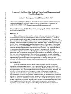
5 3. The operational process model may be established for the purpose of quality management system, but not for the purpose of major hazards and the SMS. There is, in general, a fuzzy link between the hazards and operational activities and tasks, and even fuzzier link between risk controls and operational tasks. 1 Shell International Exploration and Production BV, Thesis HSE Manual, EP-95 0323, 1995. 2 James Reason, Human Error, Cambridge University Press, 1990. Risk Support Ltd. 2 Active Bow Tie Manual Description of Bow Tie Analysis Hazard Analysis In this example, Figure , hazard is derailment and hazard realisation is the top event passenger train derailment . The threats (that can lead to the top event) are obstruction on tracks , rolling stock faults , track faults , etc. The possible consequences of this event could be injuries and fatalities , damage to trains and tracks , etc.
6 Figure derailment Bow tie To protect from threats, barriers are provided (denoted by a box with a thick black bar on the right), Figure The barriers against obstructions on tracks are to ensure operational tracks and regular track inspections . However, the barrier ensure operational tracks may decay because of the inadequate maintenance , or may fail due to obstructions due to track maintenance . This barrier decay/failure mode3 is denoted by the box with the thick red line at the bottom. If the barrier decay/failure mode is identified than it may be required to provide a secondary barrier to prevent the decay/failure mode. These secondary barriers reinforce primary barriers (which protect from threats). The numbers of the primary and secondary barriers are governed by the risk acceptance criteria. 3 Barrier decay/failure mode is also called Escalation factor ( in Thesis) Risk Support Ltd.
7 3 Active Bow Tie Manual Figure Barriers and Barrier Decay/Failure Modes Drivers reportobstructionsZ1 / reportobstructionsZ1 / or blownobjects on tracksRegular trackins pectionsX2 / 3 / materialsare not left ontracksV1 / dueto trackmaintenanceEnsureoperationaltracksX 1 / ontracksEnsure soundrolling s tockRolling stock faultsRegular trackins pectionsEns ure quality of tracksTrack faultsD PassegerTrain derailment Risk Support Ltd. 4 Active Bow Tie Manual The barriers with different coloured bars on the right hand side are intended to represent different type of barriers, or groups of workers, subcontractors, etc. Similarly, if all barriers are breached, and the top event (loss of control) is reached, then (protection / mitigation) barriers should be provided to protect from top event and/or mitigate unwanted consequences. These barriers and their decay/failure and are treated in the similar way as the barriers on the left-hand side of the bow tie.
8 Process Model In parallel with the bow tie risk analysis, the systems model is developed which describes all processes of the Company. Furthermore a set of activities and tasks are identified required to keep the process functioning on a daily basis. For each activity and each task within an activity responsible persons is identified. The duty of a responsible person is to carry out the task/activity in a specified manner and record any deviations. The development of the process model is iterative and in many cases the risk model drives the new tasks and vice versa. Linking Risk and Process Models In the next step the tasks are matched to the barriers. This means that for each barrier there should be a task the purpose of which is to ensure that the barrier is operational at all times. This process is also iterative and may require some matching before a proper link between the task and the barrier is established.
9 In Figure , in the lower part of the barrier box, the post indicator of the responsible person (or contractor s organisation) and the corresponding tasks shown ( X1, X2, Y1, etc denotes personnel group and position, and denoted task 2 of activity ). As mentioned before the development of bow tie risk model and the corresponding process model proceeds in an iterative manner. The activities and tasks taken to ensure that risk controls are effective at all times are called safety-critical . An activity comprises a set of tasks with the same management objective. Integrated Safety Management System The operational part of the safety management system (SMS) can now be developed as a natural extension of the above approach. In fact, each activity with its set of tasks represents a procedure in the old sense, except that each task is hard wired to the corresponding risk barrier. Therefore to close the continuous improvement loop, the following components of the SMS, shown in Figure , are added: Management objective for the activity and action required to implement it, Performance indicators and criteria for measuring the execution of tasks, Risk Support Ltd.
10 5 Active Bow Tie Manual Feedback loop for the improvement and operational changes, Input and output for the activity; for example, if the absence of a written procedure could result in infringement of the safety policy or breaches of legislative requirements or performance criteria, then the additional procedure represents an input for the activity. Similarly, output from an activity may represent the input for another activity, etc. Figure Safety Critical Activity ACTIVITYTask iTask jTask kBarrier lBarrier mBarrier nPERFORMANCECRITERIAPERFORMANCEINDICATOR SMANAGEMENTOBJECTIVESMANAGEMENTACTIONSRE VIEW &IMPROVEINPUT /PROCEDURESOUTPUTPLANDOCHECKFEEDBACK In associating tasks with risk controls, distributing responsibilities, defining objectives and the sources and means of measurement, the integrity of the management system is demonstrated. A similar approach can be utilised to extend the safety management system to cover the management and organisational aspects.