Transcription of RIVET HANDBOOK
1 RIVET HANDBOOK BLIND RIVETS RIVET HANDBOOK PAGE 2 Introduction 5a RIVET Fastening Explanation of blind side fastening Concepts Installation Grip Range Break Loads Galvanic Corrosion Removal of Blind Rivets Standards 5b Rivets Material types Sizes and codes Mechanical properties Head types Special types 5c RIVET Tools Hand tools Pneumatic toolsBLIND RIVETS RIVET HANDBOOK PAGE 3 5a RIVET Fastening Concepts Introduction Although bolting is the most common from of fastening in the world, it is restricted in usage because of the need to screw a nut on the end.
2 There are many applications where the back of the job cannot be accesses, such as fastening to tubing or walls. In these cases, the most common solution is to use Blind Rivets to fasten the job. Blind rivets are termed so because there is no need for access to the rear or blind side of the joint. The use of rivets in fastening most applications has been proven to be superior and extremely cost effective when compared with other methods of fastening. Welding, sheet metal screws, bolts and nuts and solid rivets all require extensive labour. There are three main reasons why blind rivets are used. 1. Low Installed cost. Up to 15 rivets per minute can be installed without any specialised labour. The unit cost is also much lower than other types of fastener. 2. Versatility Blind rivets are available in many types, sizes and materials to meet the requirements of the most demanding applications. 3. Reliability Materials are permanently clamped and provided the correct RIVET is used can withstand severe vibration and environmental conditions.
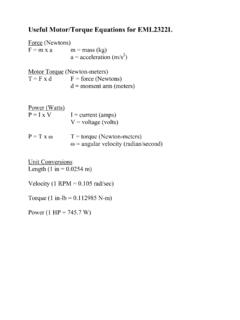
3 However, blind rivets are limited in their individual strength and should only be used when fastening relatively light gauge materials. BLIND RIVETS RIVET HANDBOOK PAGE 4 5A RIVET Fastening Concepts The Installation Process of Blind Rivets Blind rivets are a two-part fastener consisting of a shell and a headed stem (mandrel) assembled so the shell can be placed into the work to be fastened. The RIVET is set by drawing the stem through the shell, which causes the shell to deform and clamp the material securely. After the desired clamping force is achieved, the stem breaks off and is discarded. A small portion of the stem remains trapped in the bottom of the shell to ensure the clamping force is retained in the joint. Withdrawing the stem is done with special tools operated by hand, pneumatics or electricity. Figure 5a-1 shows the stages of application. Break Load The load required to break off the stem is governed by the amount of shell deformation required and a groove cut to a specific diameter just back from the end.
4 The break load is designed to prevent too much force being developed which may damage the material being fastened. Too little clamp force may fail to secure the joint. Similar to a bolted joint, a blind RIVET develops a clamping force to secure the joint members. It is crucial that the mandrel not break at a load lower than the clamping force. If this occurs. The integrity of the joint may be compromised. Grip Range Blind rivets are designed to clamp together specific thicknesses of material. The amount of deformation in the shell during setting depends upon this grip range (figure 5a-2) If the grip range is less than it should be (the RIVET is too long), excessive material will be left on the blind side and more pulls will be required to break-off the mandrel. If the grip range is too large ( RIVET is too short), insufficient material may be left on the blind side to secure the joint. Figure 5a-1. The RIVET is set by drawing the stem through the 5a-2.
5 Grip Range BLIND RIVETS RIVET HANDBOOK PAGE 5 5a RIVET Fastening Concepts Galvanic Corrosion When dissimilar metals come into contact in the presence of an electrolyte, a galvanic action occurs which corrodes one metal at a faster rate and the other more slowly. The rate of corrosion depends upon a) the difference in electrical potential, b) the conductivity of the electrolyte and c) the relative sizes of the contacting areas. Blind rivets are regularly used with dissimilar metals such as aluminium , stainless steel, mild steel, zinc-coated steel and copper. In applications high in moisture content such as air conditioners and marine environments particular care needs to be taken to minimise the effect of galvanic corrosion. The following table illustrates which metals should and should not be used together. Metal Joined RIVET Shell Material aluminium Al/Zn Coated Steel Zinc Coated Steel Stainless Steel Copper Brass aluminium YES YES ?
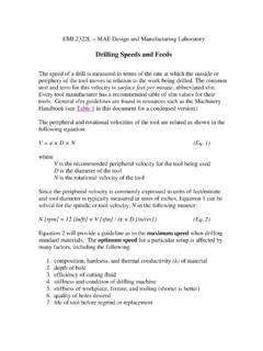
6 NO NO NO Steel Z/P NO YES YES NO NO NO Nickle Copper NO NO NO YES YES YES Stainless Steel ? ? ? YES YES YES Copper NO NO NO YES YES YES o Compatible o Incompatible. Must not be in contact with each other. o Compatible in rural and mild environments. Some corrosion may occur in marine or industrial environments. Painting both metals could reduce the reaction. Avoiding Galvanic Corrosion When galvanic corrosion becomes a threat to the serviceability of the joint, the following suggestions may be worth considering. 1. Avoid dissimilar metals by careful selection of rive shell material 2. Build a barrier between the materials such as paint, plastic washers or gaskets. 3. Make provision for drainage to allow water or other electrolyte material to escape. 4. Consider the use of anodized rivets. YESNO?BLIND RIVETS RIVET HANDBOOK PAGE 6 5a RIVET Fastening Concepts Removal of Blind Rivets If circumstances arise that requires a blind RIVET to be removed, it is recommended that the following steps be undertaken carefully or damage to the clamped material may result.
7 1. Ensure the stem is well below the RIVET head. If it appears the be flush, drive it below the head with a punch. 2. Select a drill bit with the same diameter as the recommended hole size for the RIVET , and drill through the head until enough material is removed to separate the head from the shell. 3. Punch the remainder of the shell clear of the clamped material. Figure 5a-3. Removal process for blind rivets Standards There are no Australian nor International standard covering the manufacture and supply of blind rivets. The most recognised standard is IFI 114 Break Mandrel Rivets from the Industrial Fasteners Institute in the USA. Most suppliers of quality blind rivets use this specification with a few variations. Ajax blind rivets are manufactured at our own plant in Singapore and generally adhere to IFI 114. The most notable exception is the combination of shell / stem materials which can vary depending upon the aluminium alloy used.
8 Three major tests are used to ensure that rivets comply with the requirements of IFI 114, shear strength, tensile strength and mandrel break load. Other tests such as blind head formation (usually in conjunction with break load test) and mandrel retention may be performed as required. BLIND RIVETS RIVET HANDBOOK PAGE 7 5b Types of Blind Rivets Shell and Stem Materials Blind rivets owe their popularity to ease of installation and versatility. The thousands of applications that use rivets created a demand for rivets made from various types of material. Usually, the governing factors in material selection are strength, corrosion resistance and the material to be fastened. As a general rule, the shell material should be the same as the material under the head, ie, if aluminium is fastened to steel, use steel rivets. Shell Materials Aluminiun (A) Lightweight yet strong. Good corrosion resistance. Steel (S) Stronger than aluminium with a flash coating of zinc.
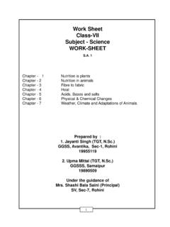
9 Stainless Steel (St) Good strength and excellent corrosion resistance. Nickel Copper (M) Excellent corrosion resistance and conductivity. The strongest blind RIVET material. Copper ( C) Relatively soft. Excellent corrosion resistance and conductivity. Figure 5b-1 contrasts the tensile strength of the various shell materials. 0500100015002000250030003500 AluminiumSteelStainlessNi CuShell MaterialTensile Strength (kN) Figure 5b-1. Relative strengths blind RIVET shells BLIND RIVETS RIVET HANDBOOK PAGE 8 5b Types of Blind Rivets Stem Materials Because the greater portion of the stem is discarded after setting, the stem material is not as crucial, save that it must be ate least the equivalent strength of the shell material. If not, it will be unable to deform the end of the shell. Steel is the most common, although stainless and aluminium stems are available in some rivets. Part of the stem remains in the shell after setting.
10 In the case of steel, this part may rust, an undesirable attribute in many circumstances. In these cases, stainless and aluminium stems may be specified. Sizes and Codes Contrary to popular belief of many expert RIVET users, a blind RIVET will set in one application of the tool provided the correct RIVET is used for that particular job. To assist with sorting through the many varied types of blind rivets, codes are used to ensure the best part can be used for the specific application. Marketers and manufacturers of rivets usually assign their own coding systems, Ajax use an American system, which has become the industry s most recognised code. It is constructed in three parts. 73 AS 43 1. Head Type 2. Material Type 3. RIVET Size Head Type There are three basic types of head found on blind rivets. The most common is the truss head which is designated as 73 . Truss heads protrude above the face of the job and have a footprint to share the load and give an impeccable finished look.