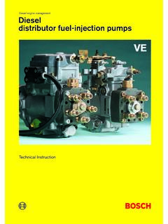
Transcription of ROBERT BOSCH MODEL PE(S)-6 MW FUEL INJECTION PUMP …
1 ROBERT BOSCHMODEL PE(S)-6 MWFUEL INJECTION PUMPSERVICE MANUALFORM CGES-375 SEPTEMBER, 1984 Printed in United States of AmericaSERVICE MANUALFORWARDThis manual is part of a series of manuals intended to assist service technicians in maintaining International Engines inaccordance with the latest technical to a commitment of continuous research and development some procedures, specifications and parts may be alteredto improve International products and introduce technological revisions may be made to this publication and mailed automatically to "Revision Service" subscribers. Thefollowing literature supporting the 400 Series Diesel Engine is available from:International Harvester CompanyForward RequestsPrinting, Procurement and Distributionto:807 Blackhawk DriveWestmont, Illinois 60559 FORM Series Engine Service Manual1 171 575 R1DT/DTI-466C Diesel Engine Operation ManualCGES-240-3 Diesel Engine Diagnostic ManualCGED-365 Diagnostic Form (DT/DTI-466C)CGES-375 Printed in United States of AmericaSERVICE MANUALINTRODUCTIONThis manual is arranged in sections with the pages numbered consecutively in each section.
2 Any drawings are alsonumbered consecutively in each section. Included at the top of each page is the section title, section number and pagenumber. The bottom center of each page will show the manual form ( CGES-375).NOTE: Future revisions will be indicated by a dash one, dash two, etc. after the form number ( CGES-375-1 will berevision number one).An index arranged according to sections will be found at the beginning of this manual. This manual is divided into sixsections which are:SECTION ONE --General Pump InformationSECTION TWO-DisassemblySECTION THREE-Cleaning and InspectionSECTION FOUR-ReassemblySECTION FIVE --CalibrationCGES-375 Printed in United States of AmericaSERVICE MANUALTABLE OF CONTENTSSECTION 1 - GENERAL Flow.
3 2 - View of View of Governor ..4 Governor Disassembly ..6 Pump Disassembly ..9 SECTION 3 - CLEANING AND INSPECTIONI nspection 4- REASSEMBLYPump 5 - CALIBRATIONC alibration Stand Maintenance .. Sheets and Calibration ChartsPump Part No. 1 802 608 in United States of AmericaSERVICE MANUALGENERALS ection 1 Figure 1. ROBERT BOSCH MODEL MW Fuel INJECTION Stop Governor Supply Priming Idle Pointer Number ROBERT BOSCH MODEL PE(S)-6MW INJECTION Pump isused on the International DT-466C diesel INJECTION pump is an in-line, plunger type, with anindividual plunger and barrel pumping element for eachengine cylinder. The INJECTION sequence is 1,5, 3, 6, 2, INJECTION pump assembly incorporates mechanical,flyweight type RQV variable speed pump throttle lever and the high-speed stop screware located on the left side of the governor fuel shut off lever is also located on the left side ofthe INJECTION pump is located on the left side of theengine.
4 High pressure lines connect the pump to thenozzles. Operating and service instructions for thenozzles are given in CGES-200-2 Service of INJECTION pump and governor can bemade by referring to two nameplates, one on the rear ofthe governor housing, and one on the front top left of theinjection pump (Figure 2). The nameplate on the rear ofthe governor gives the IH part number of the completepump and governor assembly and the ROBERT Boschgovernor number, size and rating. The nameplate on theleft side, gives the ROBERT BOSCH pump PRINCIPLESThe INJECTION pump is the in-line type with an individualplunger and barrel pumping element for each enginecylinder. Each plunger stroke is constant, but itseffective pumping (metering) stroke is variable and iscontrolled by the positioning of a common control rackconnected through linkage to the governor and thevehicle s throttle individual plunger and barrel pumping elementsreceive fuel at supply pump pressure from the injectionpump housing fuel gallery, and forces it under very highpressure through the INJECTION nozzles into the enginecombustion INJECTION pump plungers are moved by tappetassemblies which ride on the lobes of the INJECTION pumpcamshaft.
5 The INJECTION pump camshaft is timed to theengine to inject fuel into each cylinder at the proper in United States of AmericaPage 1 SERVICE MANUALGENERALS ection 1* Code for ROBERT BOSCH governor numberRQV 350 1200 MW 43-5:R= Flyweight governorQ= Fulcrum lever modelV= Variable speed governing (all-speed)350= Low idle pump speed1200= Full load rated speedMW= Fits on "MW" size pump43-5= Application number** Code for ROBERT BOSCH combination numberPES 6MW 100/320 RS 1108:PE= inline INJECTION pumps = Flange mounted6= Number of cylindersMW= "MW" size pump100= Plunger diameter in 1/10 mm/= Pump model320= Number code for location of feedpump and governorR= Rotation of pump as seen from driveend (right hand clockwise)S1108 = Application numberFigure 2. INJECTION Pump IdentificationEach plunger has a delivery valve above the delivery valve, which is held on its seat by springpressure, prevents fuel from draining out of the highpressure line between pumping INJECTION cycle can be described by observing theplunger in its four principle positions in the barrel.
6 Thefour positions are shown in Figure bottom dead center the plunger is held down on thelowest point of the cam lobe by the plunger spring. Topof plunger is below the charging port of barrel. Fuel atsupply pump pressure flows through the charging port tofill the area above the 3. Four Principle Plunger Positions of Dead Center3. Closure4. End of InjectionPort closure begins when the rising plunger covers thecharging port and fuel is trapped above the of INJECTION occurs as the plunger continues withcharging ports covered, fuel is forced upward under highpressure, unseats the delivery valve and is injected intothe of INJECTION occurs when the plunger moves up tothe point where the charging port is again uncovered bythe lower helix.
7 Fuel pressure above the plunger isrelieved to the charging gallery. This pressure dropallows delivery valve and INJECTION nozzle to seat thusending in United States of AmericaPage 2 SERVICE MANUALGENERALS ection 1 Figure 4. Fuel System FlowFUEL SYSTEM FLOWAs fuel travels through the fuel system, it will be undersuction (negative pressure), intermediate pressure, highpressure ( INJECTION pressure) and low pressure (Figure4).Negative PressureThe piston type supply pump creates a suction at its inletand pulls fuel from the fuel tank, through the fuel supplylines and through the primary fuel filter. No filter is usedon the fuel suction line extending into the fuel tankbecause wax particles could plug the filter in coldweather.
8 Fuel lines and fittings between the supplypump inlet and the fuel tank must be a minimum ofthree-eighths inches inside diameter. Small diameterfuel supply lines or fittings will reduce fuel flow and canreduce engine power PressureThe supply pump produces an intermediate pressure,called supply pump pressure, at its outlet and forces fuelthrough the final fuel filter and into the INJECTION pumphousing. Fuel under intermediate pressure surroundseach barrel assembly. Fuel pressure in the housing iscontrolled by the orificedfitting in the fuel return hose located "downstream" of thefuel return check valve and the supply pump pistonspring calibration. A special rubber hose between thefinal filter outlet and the INJECTION pump housing dampenspressure waves from the supply pump.
9 Substitute hosescan cause lower engine power even though supply pumppressure can be within PressureThe INJECTION pump meters and delivers fuel at highpressure, up to an instantaneous 9000 psi pressure afternozzle valve opening, through the INJECTION pipes or linesto the INJECTION nozzle assemblies. This high pressurefuel causes the nozzle valve to open and fuel flowsthrough the nozzle orifices into the combustion amount of fuel delivered is controlled by the injectionpump governor. A small amount of low pressure fuelreturns from the nozzle assemblies to the fuel tankthrough the leakoff PressureAn orifice fitting in the end of fuel hose from the fuelreturn check valve limits the amount of fuel returned tothe fuel tanks.
10 After fuel passes through the orifice, it isat low in United States of AmericaPage 3 SERVICE MANUALGENERALS ection 1 METERINGM etering (providing proper amount of fuel to meet enginerequirements at various loads and speeds) isaccomplished by rotating the plunger in its barrel tochange the effective pumping stroke. The effectivestroke is the distance traveled upward by the plungerfrom the time the charging port is covered until it is againuncovered by the lower helix. A short effective strokemeans a small amount of fuel is injected. As effectivestroke increases, the amount of fuel injected metering function can be described by observing therelationship of plunger helix to barrel charging port undervarious metering positions as shown in Figure 5.
