Transcription of ROOF WINDOW ELECTRIC OPERATION RETRO FIT KIT
1 roof WINDOW . ELECTRIC OPERATION . RETRO FIT KIT. IMPORTANT. INFORMATION. safety Function The kit must not be used until it has been This WINDOW may be manually operated by installed using these instructions. removing the pin and clip from the back of the The remote control should be kept out of ventilation handle when the WINDOW is open or by reach of children. removing the domed nut on the ventilation handle when closed. If repair work is required, disconnect the transformer plug from the mains supply. In case of snow and /or ice, the OPERATION of the WINDOW may be obscured. Installation in rooms with high levels of humidity should be in accordance with Product relevant electrical regulations. The transformer plug must not be removed and Kit is for indoor use only. mains voltage fed directly to the ECU. The transformer plug must not be covered Disposal of electrical product must be in (maximum temperature of 40 C).
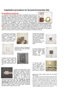
2 Conformance with national waste regulations. The packaging can be disposed as normal household waste. Maintenance and service If installed and operated correctly in accordance with the fitting instructions, the kit does not require any maintenance. It is recommended that KEYLITE service engineers carry out any repair work to the WINDOW or Keylite ELECTRIC Kit. RF-ECU-2013-C. KIT CONTENTS. A. WINDOW motor, bracket & cable B. Blind contact A. C. Transformer cable D. Control panel (ECU). E. Remote control and holder B. F. Transformer plug G. Rain sensor C. E. D. I. H. J F. G. FIXING BAG. H. Chain fixing bracket, screw and nut I. Motor chain retaining pin and clip J. 15mm screws (x9). TOOLS REQUIRED. Battery drill PZ2 Bit 10mm Drill bit 4mm Drill bit 3mm Drill bit 10mm 4mm 3mm P21 Screwdriver 2. PREPARATION. The blind contact It is strongly recommended that you install the blind contact even if you do not currently have a blind fitted.
3 Tools required shown on Page 2. 1. Remove the lid from the blind contact by undoing the screw using the P21 screwdriver. 2. Open WINDOW using the ventilation handle at the top. 3. Place the blind contact body over the top left hand corner of the sash making sure the contact is pushed towards the locking bolt and the centre of the sash. Using the 3mm drill bit carefully pilot the two holes in the timber. 3. PREPARATION. 4. Secure the blind contact set using two 15mm screws provided. Replace the lid back onto blind contact and secure using screw. 5. Remove the hood flashing from the WINDOW frame. 6. Mark point X on the plasterboard above the WINDOW . X. 30mm X. 20mm 7. Using the 10mm drill bit and power drill carefully drill through the plasterboard at point marked X above the WINDOW to create a path for the transformer cable. Make note to keep the drill bit X. parallel with the frame timber when drilling.
4 4. PREPARATION. Power supply 8. Take the transformer power cable and feed the X. white plug on the end through the hole made above the roof WINDOW at point X . 9. Feed the end of the cable through to the outside of the WINDOW . 10. Take the white transformer plug and connect into the PW jack on the ECU. Make sure the cable is routed as shown. Rain sensor 11. Take the blue plug on the end of the rain sensor and connect in to the RS jack on the ECU as shown. Make sure the rain sensor cable is routed as shown. 5. PREPARATION. 12. Turn the ECU around and then fit the rain senor cable down the front using the channel provided. Fitting the ECU. Once both the transformer and rain sensor have been plugged into the ECU and the cables routed as explained, the ECU is now ready to secure in position. 13. Offer the ECU up to the top left hand corner (from inside) using the two guides on the ECU. 14. Secure the ECU into place with three 15mm screws.
5 6. PREPARATION. Securing the rain sensor 15. Looking from the outside of the WINDOW , remove the adhesive patch from the back of the rain sensor and stick it to a clean and dry surface as shown below. Take note that the cable route follows the inside edge of the aluminium channel. Fixing the WINDOW motor 16. Working from inside the room, offer the motor complete with bracket up to the WINDOW frame. Make sure the orientation of the bracket and motor is as shown. Align the two tabs either side of the latch keep on the left nearest to the ECU. For 1140mm or 1340mm wide windows please remove the right hand latch mechanism as shown. 17. Secure the motor bracket to the latch timber using 15mm screws and battery drill with PZ2. bit attached. 18. Carefully feed the WINDOW motor cable through the route shown and connect green plug into WM' jack on the ECU. 7. PREPARATION. Programming the remote control 19. Take the transformer plug and connect the jack into the transformer power cable.
6 Connect the transformer plug into the mains and switch on. 20. Turn on the remote control. ON. OFF. 21. Press the RC button on the ECU and the LED. above the button will flash. 22. Press any button on the remote control and the LED on the ECU will flash and extinguish. This will WINDOW -Open Blind-Open be followed by a click from the ECU. The remote control is now programmed. Open The remote Stop control OPERATION Stop works on a loop WINDOW -Close Blind-Close Close 8. PREPARATION. Attaching the motor chain to the WINDOW 23. Mark a point shown as Y on the back of the ventilation handle foam at the top of the WINDOW as shown. Y. 118mm 20mm 24. Using a battery drill and the 4mm drill bit carefully drill through the foam of the ventilation handle and the back section. Stop when the drill bit is visible from the inside. Make sure drill bit is at right angles to the ventilation handle. 25. Place the bracket onto the foam of the ventilation handle over the hole.
7 Place the bolt though the hole. Compressing the foam with the bracket until the threads of the bolt are visible from wire. Attach the domed nut to the thread as shown. 9. PREPARATION. 26. Press the button on the remote control to extend the chain from the motor. 27. When the motor chain is fully extended connect to the ventilation handle using clip and pin. 28. Press the button on the remote control to close the WINDOW . The WINDOW is now connected and operable via the remote control. 10.