Transcription of ROTARY (VANE) VACUUM PUMP - IIT Kanpur
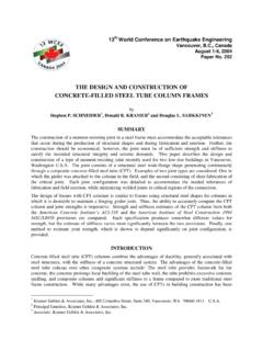
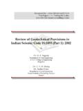
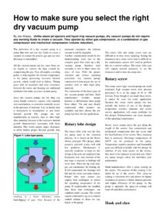
1 ROTARY (VANE) VACUUM PUMP A ROTARY vane VACUUM pump is an oil-sealed ROTARY displacement pump. The pumping system consists of a housing (1), an eccentrically installed rotor (2), vanes that move radially under spring force (3) and the inlet and outlet (4). The outlet valve is oil-sealed. The inlet valve is designed as a VACUUM safety valve that is always open during operation. The working chamber (5) is located inside the housing. Rotor and vanes divide the working chamber into two separate spaces having variable volumes. As the rotor turns, gas flows into the enlarging suction chamber until it is sealed off by the second vane. The enclosed gas is compressed until the outlet valve opens against atmospheric pressure.
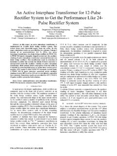
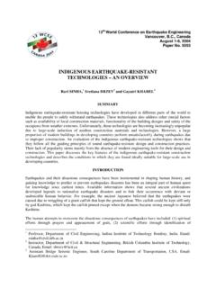
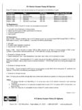
2 In the case of gas ballast operation, a hole to the outside is opened, which empties into the sealed suction chamber on the front side. The Rotor moves with the help of a motor attached to it. Animation video of the working of a ROTARY (vane) pump Animation video of the working of a Trivac ROTARY (vane) pump DIAPHRAGM VACUUM PUMP Diaphragm VACUUM pumps are dry positive-displacement pumps . A crankshaft-driven connecting rod (4) moves the diaphragm (1) that is tensioned between head cover (2) and housing (3). The space between the head cover and the diaphragm forms the suction chamber (5). Diaphragm pumps require inlet valves and outlet valves (6) to achieve gas displacement.
3 Pressure-controlled shutter valves made of elastomer materials are used as valves. First the diaphragm is pulled down, creating low pressure in the suction chamber. The inlet valve (left valve) opens and gas is sucked into the chamber. Because of high pressure on the exhaust side (right valve), it remains closed. Because the suction chamber is hermetically sealed off from the drive by the diaphragm, the pump medium can neither be contaminated by oil nor can aggressive media corrode the mechanics. The harmful space between the outlet valve and the suction chamber results in only a limited compression ratio. This means that an ultimate pressure of only approximately 70 mbar can be attained with a single pump stage.
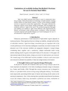
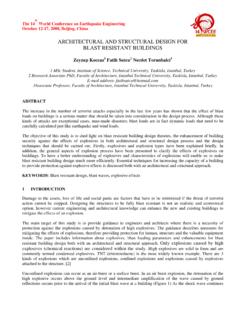
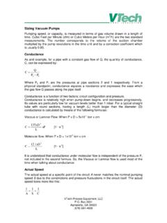
4 Connecting multiple pumping stages in series can reduce ultimate pressure to mbar. Lower pressures cannot be achieved, as in this case there is no longer sufficient force to open the inlet valve. SCROLL VACUUM PUMP Scroll pumps are an excellent alternative to ROTARY vane pumps where oil free pumping is desirable. The ultimate VACUUM achieved by a Scroll pump is 1x10⁻² mbar. A scroll pump (also called as a spiral compressor, a scroll pump or a scroll VACUUM pump) is a device for compressing fluids such as liquids and gases. A scroll pump uses two interleaved Archimedean spiral scrolls to pump, compress or pressurize fluids. One of the scrolls is fixed, while the other orbits eccentrically without rotating, thereby trapping pockets of gas molecules between the scrolls.
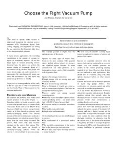
5 Video of the working of Edwards Scroll VACUUM Pump OIL DIFFUSION VACUUM PUMP The oil diffusion pump is operated with an oil of low vapor pressure. A high speed jet of the Oil is generated by boiling the Oil and directing the vapor through a jet assembly. Note that the oil is gaseous when entering the nozzles. Within the nozzles, the flow changes from laminar, to supersonic and molecular. Often several jets are used in series to enhance the pumping action. The outside of the diffusion pump is cooled using either air flow or a water line. As the vapor jet hits the outer cooled shell of the diffusion pump, the working fluid condenses and is recovered and directed back to the boiler.
6 The pumped gases continue flowing to the base of the pump at increased pressure, flowing out through the diffusion pump outlet, where they are compressed to ambient pressure by the secondary mechanical forepump and exhausted. Diffusion pumps cannot discharge directly into the atmosphere, so a mechanical forepump is typically used to maintain an outlet pressure around mbar. Diffusion pumps have no moving parts and as a result are quite durable and reliable. They can function over pressure ranges of 10 10 to 10 2 mbar. They are driven only by convection and thus have a very low energy efficiency and low cost per unit pumping speed when compared with other types of pump used in the same VACUUM range.
7 One major disadvantage of diffusion pumps is the tendency to backstream oil into the chamber being evacuated. This oil can contaminate surfaces inside the chamber or upon contact with hot filaments or electrical discharges may result in carbonaceous or siliceous deposits. Generally cold traps and baffles are utilized between the chamber and the diffusion pump to minimize backstreaming, although this results in some loss of pumping ability. The oil of a diffusion pump cannot be exposed to the atmosphere when hot. If this occurs, the oil will burn and has to be replaced. Animation video of the working of a Diffusion pump TURBO-MOLECULAR VACUUM PUMP (TMP) A turbo-molecular pump (TMP) or turbopump reduces the pressure of the chamber to which it is connected from about 10-2 Torr to about 10-8 Torr.
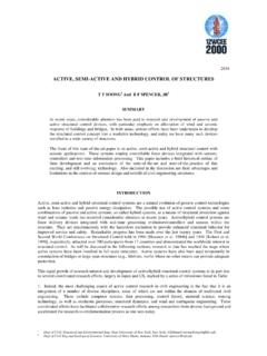
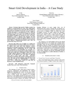
8 A TMP consists of a stack of rotors with blades, or slots, depending on the specific pump. In between rotor disks are stators, fixed discs that contain the same blades, or slots, as the rotors, but oriented in the opposite direction. The motor makes the rotor spin about the axis. The stators are fixed disks in between rotors, and the vent is a hole through which we can let a gas through if we wish to bring the pump back to a higher pressure. The big arrows show the flow of pumped molecules from the attached chamber. When the blades, spinning at 20000 rpm (about 2100 rad/s), hit the molecules, they impart momentum on these. Because of the angle of orientation of the blades of the rotor and the stator, the molecules move down to the next rotor.
9 This succession of rotor-stator pairs drives the molecules towards the exhaust, where they are collected by a backing pump. When the chamber is at atmospheric pressure, the flow of gases is described as "viscous flow", where the molecules move in bulk and interact with each other much more significantly than they do with the walls of the container. Most turbopumps cannot work in this regime. The reason is the force exerted by a blade on a molecule is not significant compared with the collisions between the molecules, and so the general flow remains unaffected. For this reason, a ROTARY pump has to remove the gas molecules before the turbopump is turned on, down to about 10-2 Torr.
10 At this pressure, the flow is called "molecular flow", meaning that molecules are relatively free and, to a good approximation, do not interact with each other. In this regime, the turbopump imparts momentum on the gas molecules independently, so they can properly go move downwards towards the other end of the pump. Once turned on, the turbopump will work for quite a long time reducing the chamber pressure, until at some point the pressure will not go down significantly any longer. This happens between 10-6 and 10-8 Torr. Video of the working of Oerlikon-Leybold Turbo-Molecular Pump Video of the working of Agilent VACUUM TechnologyTurbo-Molecular Pump Parts of Agilent Technology TMP ION GETTER VACUUM PUMP (IGP) The ion pump operates between pressures ranging from 10-4 mbar to 10-10 mbar.