Transcription of Router Table Plans - Bob's Woodworking Plans - BobsPlans.com
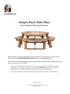
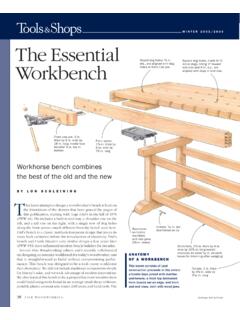
1 Table PlansIncrease the capabilities of your Router with this weekend project. Features a sliding fence with EZ-Mountclamps. These clamps are simple to make and grip tightly and quickly. They make the fence easy to positionfor accurate cuts. The top and fence plates are made of countertop material. The frame and bit holder, are madeof stock. Either hardwood or pine works fine. The extensive use of pocket holes makes the assembly of this project easy and intuitive. If you have never usedpocket holes in your Woodworking projects, you ll wonder how you ever got by without them. Pocket holejoints are extremely strong and there is no measuring. You simply drill the pocket holes in one of the workpieces to be joined, (the exact location is not critical), clamp the pieces together and insert the screws. Since thescrews remain in the joint, they serve as both a dowel and a permanent lift out Router plate allows easy access to the Router and bit. Plus, there are several accessory platesavailable that let you use a jig saw, pocket hole jig, and spindle sander with this Table .
2 It also features a mitergauge slot. Links for the items you ll need are included in the sponsors pages, along with several 2005 by Robert E. ReedyAll rights reservedTable of ContentsPlease read and follow all tool manufacturers safety and operating instructionsbefore operating equipment. Always wear eye and hearing List .. 1 Router Table Parts (A) .. 2 Router Table Parts (B) .. 3 Router Table Parts (C) .. 4 Router Table Parts (D) .. 5 Assemble the Sides .. 6 Attach the Stiffeners & Legs .. 7 Attach the Feet .. 8 Bit Organizer Parts .. 9 Assembling the Bit Organizer .. 10 Fence Base Drawing (A) .. 11 Fence Drawing (B) .. 12 Stationary Faces Drawings .. 13 Support Blocks & Sliding Fence Plates .. 14 Vacuum Box and EZ-Mount Clamps .. 15 Assembling the Fence (A) .. 16 Assembling the Fence (B).. 17 Assembling the EZ-Mount Clamps .. 18 Legs Full Patterns (Top Section) .. 19 Legs Full Patterns (Bottom Section) .. 20 IntroductionThank you for purchasing our Router Table Plans .
3 I hope you find this Router Table to be arewarding and satisfying project. For the prototype, the top and sliding sub fences were madefrom some old Table top material I had lying around. I chose this material because it was nice andflat and wood slides easily over it. MDF (Multi-Density Fiberboard) is an excellent choice material you use, make sure it is flat or you won t get accurate cuts when using can make the rest of the parts from any type of wood you choose. I used popular but pinewould work too. You can purchase all the parts and accessories you ll need from the companieslisted on the sources List Page 1 Router Table Materials List Qty Size Material Item Name 1 22" X 16 1" Countertop material or MDF Top 2 18" X 2 1/4" 3/4" Stock Front/Back 2 10 1/2" X 2 1/4" 3/4" Stock Ends 1 15" X 2 3/4" 3/4" Stock Front Stiffener 2 16 1/2" X 1 1/4" 3/4" Stock Rear Stiffener 2 16" X 3 1/2" 3/4" Stock Feet 2 12" X 5 1/2" 3/4" Stock Legs 1 15" X 4 1/4" 3/4" Stock Bit Organizer Top 1 15" X 2 3/4" 3/4" Stock Bit Organizer Bottom 2 15" X 1 1/4" 3/4" Stock Bit Organizer Sides 1 25" X 4" 3/4" Stock Fence Base 2 10 1/2" X 3" 3/4" Stock Stationary Fence Faces 2 12" X 4" 1" Stock Sliding Fence Plates 2 2 1/2" X 2 1/2" 1" Stock Square Fence Support Blocks 2 1 1/2" X 1 1/2" 1" Stock Beveled Fence Support Blocks 1 6" X 2 1/2" 3/4" Stock Vacuum Box Rear 1 6" X 2 7/8" 3/4" Stock Vacuum Box Top 2 1 1/2" X 1" 3/4" Stock EZ-Mount
4 Clamp Riser 2 1 1/2" X 3" 3/4" Stock EZ-Mount Clamp Block 1 8 " X 11 3/4" 1/4" Aluminum Router Plate 1 22" by 1" 1/2" Aluminum Miter Gauge Track 1 N/A Plastic Bit Safety Guard 1 48" X 3/4" 1/2" Aluminum T-Track T-Track Knobs and Bolts Copyright 2005 by Robert E Reedy, Vandalia, Ohio All Rights reserved 22"16"Top1 (Required)18"2 1/4"2 1/4"10 1/2"Holes are 5/16" diameter, 3 1/2" from ends, 3 1/2" between centers, and 1 1/4" from Table Parts - (A)Page 2 All Rights ReservedCopyright2005 by Robert E. Reedy, Vandalia, OhioCThe front, back, and sides are made from 3/4" material. Drill the pockets holes as shown above. The exact location of the pocket holes is not top is made from 1" thick countertop material.
5 I chose this material because I had some I saved from an old office Table . It was nice and flat and showed no signs of warping. If you don't have access to 1" thick material, you can make do with 3/4" stock. But the material must be flat. You can probably find some MDF board that is stable and (Required)Ends2 (Required)5 1/2"12"Holes are 1/4" diameter, 1" from ends, 3 1/2" between centers, and 1 1/4" from Holes are 1 1/4" from (Required)Legs2 (Required)16"3 1/2"6 1/4"1" from edgeRouter Table Parts - (B)All Rights ReservedCopyright2005 by Robert E. Reedy, Vandalia, OhioC15"2"1"7 1/2"16 1/2"1 1/4"2 3/4"Front StiffenerRear StiffenerThe stiffeners, legs, and feet are made from 3/4" 3 Router Table Parts - (C)4 3/4"5 1/8"Figure 1 Figure 2 Figure 3To cut out the recess for the Router plate, make a frame to guide your Router as shown in Figure 1 below. You'll need a 3/4" wide straight bit for this. To determine the dimensions of the frame, make a practice cut as shown in Figure 2.
6 Measure the distance "X" from the slot to the edge guide. The height of the frame should be 8 1/4" plus two times the distance "X" and the width of the frame should be 11 3/4" plus two times distance "X". For my Router , the inside dimensions of this frame turned out to be a little more than 13" by 16". But your Router may be different so be sure to get the exact measurement and make your frame accordingly. You can assemble the frame with pocket holes as shown in Figure 1. Clamp the frame to the countertop material so the cutout will be centered side to side and the front of the cutout will be 4 3/4" from the front edge of the material. This allows room for the miter guage the Router to cut a slot about 5/16" deep. (The Router plate is 1/4" thick but you need to have the recess a little deeper so you can set it to be flush with the Table surface. You do this by putting a flathead screw in each corner as shown in Figure 3. Then, you can adjust the screw height so the plate is flush with the top on all four corners.)
7 Be sure the frame and workpiece are securely clamped to a solid work Table or workbench and follow all safety precautions that came with your Router . Never use power tools without safety glasses and don't wear loose clothing. Your clothing can get caught up in moving parts with any type of power tool. Continued on next Rights ReservedCopyright2005 by Robert E. Reedy, Vandalia, OhioCPage 411 3/4"8 1/4" Router Table Parts - (D)All Rights ReservedCopyright2005 by Robert E. Reedy, Vandalia, OhioCYou can remove the center of the cutout with a jig saw. Try to leave as much material around the edge as possible. If your jig saw blade makes a 1/16" wide cut, the recess should have about an 11/16" wide edge around it. Wait until the stiffeners are installed before putting the corner adjustment screws in a slot 1" wide by 1/2" deep and 3 1/4" from the front edge as shown above. 3 1/4"Page 5 Assemble the SidesAll Rights ReservedCopyright2005 by Robert E. Reedy, Vandalia, OhioCAssemble the four sides with a pocket hole screw in each corner as shown above.
8 Page 6 Attach the assembled sides to the underside of the top with pocket hole screws. It should be centered from front to back and side to the Stiffeners & Legs to the TopAll Rights ReservedCopyright2005 by Robert E. Reedy, Vandalia, OhioCAttach the legs with 1/4" by 2" carriage bolts as shown. The slightly larger holes in the sides allow you to adjust the legs to ensure they set flat on the the stiffeners to the underside of the top. StiffenersPage 7 Attach the Legs to the FeetAll Rights ReservedCopyright2005 by Robert E. Reedy, Vandalia, OhioCAttach the legs to the feet with pocket hole screws. The legs should be centered from side to side and end to end of the feet. If you are including the bit organizer, be sure the holes for the bit organizer are on the inside of the legs. Predrill a hole in each corner of the cutout and install the adjustment screws as shown above. Adjust the screws so the Router plate sits flush with the surface of the Table top. Next, install the miter guage with flathead screws as shown above.
9 This completes the Router Table . Now, you're ready to build the fence and bit ScrewsPage 8 Miter GaugeBit Organizer PartsAll Rights ReservedCopyright2005 by Robert E. Reedy, Vandalia, OhioCCut the top, bottom, and 2 sides from 3/4" stock. The length should be the distance between the legs. For the prototype, this was 15".Drill seven 9/16" holes along one edge of the top as shown. Then, drill eleven 9/32" holes along the other edge as shown. This will accomodate seven bits with 1/2" shanks and eleven bits with 1/4" 1/2"2"2"2"2"2"2"1 1/4"1 1/4"Page 915"2 3/4"Bottom15"4 1/4"Top15"1 1/4"Sides(Two Required)Assemble the Bit OrganizerAll Rights ReservedCopyright2005 by Robert E. Reedy, Vandalia, OhioCPage 10 Attach the top to the sides with 1 1/2" long finishing nails as shown. Then insert the bottom between the sides as shown and attach with finishing should already have two holes in each Router Table foot for attaching the bit organizer. Attach the finished bit organizer to the feet using two flathead screws from the bottom of each foot.
10 This completes the Bit Organizer. Now, you're ready to build the fence. Drill two 5/16" holes for the EZ Clamp Bolts. The 5/16" holes are 1 1/4" from each end and 1 3/4" from the rear edge. Drill two 1/4" holes 3/8" from the ends and 1 3/4" from the rear edge for the alignment dowels. These holes for the alignment dowels are only 1/2" deep and must be drilled from the botom surface of the , cut a half circle with a 1 1/2" radius as shown. This provides clearance for the Router "4"Fence BaseBegin making the base by cutting a piece 25" long by 4" wide from 3/4" 3/4"1 1/2" " Diameter1/4" Diameter1 1/4"1 3/4"12 1/2"5/16" DiameterFront3/8"CopyrightC2005 by Robert E. Reedy, Vandalia, OhioAll Rights ReservedFence Drawings - (A)Page 11On the bottom surface, drill 6 more holes for # 8 screws and countersink them. These are for attaching the fence faces. All six of these holes are 3/8" from the front by Robert E. Reedy, Vandalia, OhioAll Rights ReservedFence Drawings - (B)Page 12On the bottom surface of the base, drill 4 holes for # 8 screws and countersink them.