Transcription of RS-485 for Digital Motor Control Applications
1 Application ReportSLLA143 - May 20031RS-485 for Digital Motor Control Applications1 Clark KinnairdHPL InterfaceABSTRACTThis application report focuses on the benefits of using RS-485 signaling for Motor controland motion Control Applications . This technology has several benefits for these applicationsin terms of noise immunity, wide common-mode voltage range, adequate data rate, andmultipoint capability. Other Applications also use RS-485 signaling to take advantage of thesesame benefits. Applications such as process Control networks, industrial automation, remoteterminals, building automation and security systems apply RS-485 extensively to solve theirrequirements for robust data transmission over relatively long .. Motor Devices3.. Feedback4.. Controllers4.. Data Transmission5.. Basic Topology5.. 2 Data Transmission Concerns and How RS-485 Addresses Each6.
2 Environment7.. EMI/Noise Immunity7.. Ground Potentials/Common Mode8.. Electrostatic Discharge9.. General Ruggedness10.. Speed10.. Feedback Loop Delay10.. Propagation Delay (Cable Transmission Delay, Transceiver )10.. Signaling Rate11.. Larger Payload for Serial Communication11.. Multipoint Topologies11.. 3 Application Example12.. Encoder Feedback Signals From High-Resolution Incremental Encoder12.. 4 Conclusion13.. 5 References13.. 1 Originally featured on ChipCenter Analog Avenue at are the property of their respective for Digital Motor Control Applications1 List of Figures1 Digital Motor Control Block Diagram Showning Components Offered by Texas Instruments3.. 2 Rotary and Linear Electric Motors4.. 3 Interfaces in a Motor Control System (Single-Axis Shown)6.. 4 Receiver Function With and Without Hysteresis7.
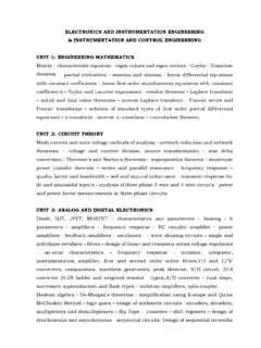
3 5 Hysteresis Eliminates Spurious Transitions8.. 6 System With Ground Potential Shift9.. 7 Typical Application, Encoder Feedback Signals12.. List of Tables1 Signals in a Typical Motion Control System5.. SLLA1433 RS-485 for Digital Motor Control Applications11 IntroductionDigital Motor Control refers to using Digital processors to Control the motion of electric one or more methods of feedback are available to the Digital processor, making this aclosed loop system (See Figure 1). This contrasts to analog Control systems and open-loopmotion Motor Control is found in many Applications . These include storage devices (such as diskdrives), industrial robotics, high-precision semiconductor manufacturing, and 1. Digital Motor Control Block Diagram Showning Components Offered by DevicesThe Motor involved in Digital Motor Control may be one of several types.
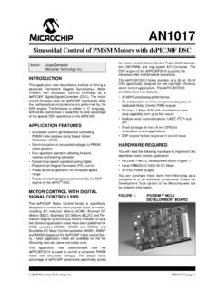
4 The most common isthe subfractional horsepower rotary Motor (see Figure 2a). These may be further classified asac, dc brush, or dc brushless type, depending on the method of commutation. Small motors aretypically sized according to their frame size and power in watts. Larger motors, typically ac type,are classified by their power in horsepower. Although rotary motors are the most common, otherconfigurations are available, such as linear motors (see Figure 2b), and gearhead motors withvarious implementations of actuators built for Digital Motor Control Applications1(a) Rotary Electric Motor (b) Linear Electric MotorFigure 2. Rotary and Linear Electric order to provide feedback on the position, speed, torque or other dynamic properties of themotion system, feedback sensors are necessary. Perhaps the most common feedback sensor isa rotary encoder, consisting of a wheel with alternating stripes, mounted on the Motor shaft.
5 Asthe Motor rotates, an optical sensor detects the passing of the stripes, and produces electricalsignals, which a controller can use to determine the Motor s motion. Other types of sensors aretachometers, synchros and resolvers, which are induction-based sensors, Hall-effect sensors,which are magnetic-based, and potentiometers, which are matter which sensor method is used, the Digital controller must repetitively sample thesensor signal, in order to constantly maintain current knowledge of the system s dynamicmotion. Depending on the system requirements for speed, dynamic response and accuracy, therate of feedback sampling may be over several thousand samples per controller, whether Digital or analog, compares the commanded motion and actual dynamicsof the system, and processes these inputs to create a Control signal to the actuator. In the caseof Digital controllers, additional tasks may include system start-up routines, diagnostics,communications Control , and sampling multiple controllers may be as complex as dedicated computer processors, or as simple assingle-chip programmed gate arrays.
6 Texas Instruments offers Digital signal processors withfeatures optimized for motion Control , and microcontrollers with varying features for best-fitsolutions to a wide array of Applications . For more information, search on Digital Control on theTexas Instruments web site at RS-485 for Digital Motor Control TransmissionThis discussion focuses on the benefits of using RS-485 signaling for Motor Control and motioncontrol Applications . As discussed below, this technology has several benefits for theseapplications in terms of noise immunity, wide common-mode voltage range, adequate data rate,and multipoint capability. Other Applications also use RS-485 signaling to take advantage ofthese same benefits. Thus Applications such as process Control networks, industrial automation,remote terminals, building automation and security systems apply RS-485 extensively to solvetheir requirements for robust data transmission over relatively long distances.
7 Often the RS-485signaling is bundled with a protocol such as Profibus, Interbus, Modbus or BACnet, each tailoredfor the specific requirements of the end signaling technologies may be used when the features of RS-485 are not the best fit. Forexample, RS-232 or RS-422 signaling may be adequate in some Applications sometimescontroller area network (CAN) or EtherNet/IP (Industrial Protocol) are preferred due tocompatibility with an existing network. For higher speed Applications , and where long distanceand common-mode voltages are not as rigorous, M-LVDS can provide lower power of these alternatives are discussed in the application note Comparing Bus Solutions,available on the TI web TopologyIn the motion Control application example shown in Figure 3, there are several differentinterfaces that may require special attention with regard to data transmission.
8 Table 1 identifiesseveral categories of signals, and summarizes the critical characteristics of signaling speed andsignal 1. Signals in a Typical Motion Control SystemSIGNALDESCRIPTIONTYPICAL SPEEDSIGNAL LEVELSM otion CommandsDigital (pulse or encoded binary)Up to 10 MbpsTTL or CMOS logicAnalogUp to the servo bandwidth ofthe system 10V typical rangeMotion FeedbackDigital (pulse or encoded binary)Up to 10 MbpsTTL or CMOS logicPosition FeedbackSynchro, Resolver (sinusoidal)Up to 10 kHz>20 VacEncoder, Digital outputs (A, B and Index pulses)Up to 10 Mbps (afterinterpolation)TTL or CMOS logicDrive VoltageMotor coil voltage, one to three phasesUp to 100 kHz depending oncommutation schemeUp to 200 V depending on motorpower and windingCommutationSignalsBinary signals, usually three phases, for determiningmotor commutation based on winding positionUp to 3 kbpsTTL or CMOS logicTool/LoadCommandsApplication-specif ic command signals, usuallycoordinated with motion trajectoryApplication specificApplication specificActuatorLimits/StatusLimit switches, interlocks, homing sensors, to 1 kbpsTTL, CMOS or up to 24 VFrom this table it can be observed that any data transmission scheme must have a wide rangeof operation to fit the spectrum of Digital motion Control needs.
9 RS-485 , with signaling from dc torates of over 10 Mbps and robust signal levels, suits most of these requirements well. Thesesignals are illustrated in Figure 3. Note this figure shows a single-axis system; multiaxis systemsmay share the same controller and have coupled mechanics to the same tool or for Digital Motor Control Applications1 MotorServoAmplifierActuator/LoadEncoderC ommutationSignalsPositionFeedbackDriveVo ltageActuatorLimits/StatusMotionCommands MotionFeedbackTool/Load CommandsControllerFigure 3. Interfaces in a Motor Control System (Single-Axis Shown)Depending on the physical arrangement of the specific application, there may be significantdistance between the controller, servo amplifiers, motors, and load. In addition to distance, otherfactors such as electrical noise, temperatures, and cable faults should be considered whendesigning these systems.
10 The goal of effective data transmission should be to provide reliablecommunication between these components, regardless of the distance or Transmission Concerns and How RS-485 Addresses EachDigital motion Control Applications pose several challenges to reaching the goal of efficient,robust communication between system components. Inherently an electromechanical actuator isinvolved, with its associated electrical noise and relatively high current levels. Safety anddependability further require that the communication path is very reliable for controlling themoving mechanism. Also associated with the moving application are constraints on cablerouting, which may require extra lengths of cabling. Stability of the servo system also putsadditional demands on the signaling rate. In the following paragraphs, the suitability of RS-485to meet these needs is RS-485 for Digital Motor Control ImmunityElectromagnetic interference (EMI) can corrupt the signals in a Motor Control system.