Transcription of RSD110-6 STEPPING MOTOR DRIVE Operation Manual
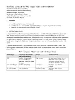
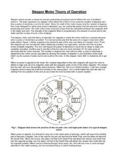
1 RSD110-6 STEPPING MOTOR DRIVE . Operation Manual 1|Page Contents Overview .. 3. Wiring Instructions .. 4. Connector Information .. 6. Configuring the DRIVE .. 11. Dimensions and Mounting Instructions .. 13. Trouble Shooting and Errors Codes .. 14. 2|Page Overview Thank you purchasing the Model RSD110-6 , STEPPING MOTOR driver. This advanced stepper DRIVE utilizes a PWM current control mode. This control mode has the following advantages over traditional stepper technologies. a. Smoother Operation b. Lower audible noise c. Lower mechanical vibration d. Lower operating temperature 3|Page Wiring Instructions The RSD110-6 stepper MOTOR drivers utilize a simple screw terminal type connector to connect the AC, MOTOR and control wires. The following instructions explain how to connect typical stepper motors, control systems and AC.
2 Sources. Fig. 1 shows a typical wiring diagram. Fig. 1 Typical wiring diagram 4|Page Tools There are only two tools necessary to connect the wires to the DRIVE . 1. Wire strippers 2. Small flat head screwdriver Wiring procedures 1. Carefully strip of the protective coating off of the wire 2. Unscrew the desired screw terminal with the small flat head screwdriver 3. Push in the wire until the protective coating reaches the edge of the screw terminal. Ensure you are not crimping any of the protective coating 4. Tighten the screw terminal with screw driver 5. Test the connection with an appropriate tug on the wire 5|Page Connector Information AC Input Connector Use this connecter to attach the wires from the AC Voltage source. Specification: AC Voltage Range: 50-110V.
3 Maximum Voltage: 120V. Max Current: RSD110-6 , (6 Amps), Caution: AC Voltages beyond this range WILL damage the DRIVE and void the warranty. MOTOR Connector Use this connector to attach the wires coming from the stepper MOTOR . This DRIVE will work with 2-phase stepper motors with 4, 6 and 8 wiring options. Wiring Options: There are 5 ways to connect a stepper MOTOR to the DRIVE . 1. 4-wire MOTOR : Connect one MOTOR phase to A + and A on the DRIVE , and the other MOTOR phase to B+ and B- on the DRIVE . (Fig. 2). 2. 6-wire MOTOR (Serial Connected): In a 6-wire serially connected stepper MOTOR the center tap is not used. Connect one MOTOR phase to A + and A on the DRIVE , and the other MOTOR phase to B+ and B- on the DRIVE . (Fig. 4). Note: If the MOTOR is connected properly the resistance will be double the phase resistance.
4 3. 6-wire MOTOR (Parallel Connected): In a 6-wire Parallel connected stepper MOTOR the center tap is used. The user must connect the A+ and A and B+ and B wires together. Then, connect one MOTOR phase to A + and A on the DRIVE , and the other MOTOR phase to B+ and B- on the DRIVE . (Fig. 5). 6|Page Note: If the MOTOR is connected properly the resistance will be half of the phase resistance. 4. 8-wire MOTOR (Serial Connected): In an 8-wire serially connected stepper MOTOR the center tap wires need to be connected together. Then, connect one MOTOR phase to A +. and A on the DRIVE , and the other MOTOR phase to B+ and B- on the DRIVE . (Fig. 7). Note: If the MOTOR is connected properly the resistance will be double the phase resistance. 5. 8-wire MOTOR (Parallel Connected): In an 8-wire Parallel connected stepper MOTOR the center tap wire need to be connected together.
5 The user must also connect the A+ and A. and B+ and B wires together. Then, connect one MOTOR phase to A + and A on the DRIVE , and the other MOTOR phase to B+ and B- on the DRIVE . (Fig. 8). Note: If the MOTOR is connected properly the resistance will be half of the phase resistance. Caution: stepper motors with 6 and 8 wiring options must have their center tap connections wired correctly or the DRIVE and/or MOTOR may be come damaged. Tip: If the stepper MOTOR wires are not labeled, use a multi-meter on the resistance setting to find the phase resistances. 7|Page Control System Connector Use this connecter to connect control systems that support the standard pulse and direction mode of Operation . Specification: Input current range: 8-15mA. Maximum input Voltage: 30V.
6 Maximum input frequency: 2000Hz Control Connector definition Dir +, - : Input connection that controls the direction of the MOTOR . The state of the control signal (high & low) will determine if the MOTOR is running clockwise or counter clockwise. The signal level should stagger the CP pulses falling edge, and the signal duration has to be greater than us. EN +, - : Input connection that controls the power to the MOTOR . The state of the control (high &. low) will determine if the MOTOR is engaged or off-line. 8|Page Pulse +, - : Input connection that controls the position of the MOTOR shaft. The state of the control signal (high & low) will determine if the MOTOR shaft turns. The maximum frequency that can be used to control the DRIVE is 2000Hz, and the signal duration has to be greater than us.
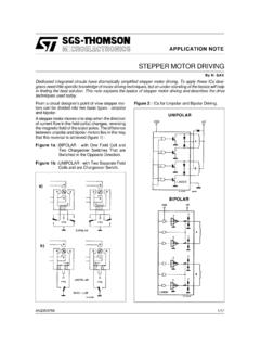
7 Caution: Control system signal must have enough current capability to DRIVE the stepper MOTOR drivers internal interface circuit directly. The internal interface circuit for the stepper MOTOR drives uses opto-couplers technology to isolate and protect the control system from the DRIVE . (Fig. 9). Fig 9 - internal interface circuit The stepper DRIVE supports a standard 5V input, however, if the users control system support 12V or 24V, please refer to table 1 to add the correct current limiting resistor. Signal Amplitude Resistor 5V None needed 12V 680 . 24V . Table 1- Resistor values There are three ways to connect an input to the DRIVE . 1. Single Ended Input (sourcing current): Connect Pulse+, Dir+, EN together and then connect to the control systems voltage source.
8 Note: depending on the control system a 1K. pull up resistor may be necessary. Then connect the control systems Pulse+, Dir+ and EN+. to the drives Pulse-, Dir- and EN- connections. 9|Page 2. Single Ended Input (sinking current): Connect the drives Pulse -, Dir -, EN-, together, and then connect to the control systems ground. Note: depending on the control system a 1K. pull down resistor may be necessary. Then connect the control systems Pulse +, Dir + and EN+ to the drives Pulse +, Dir + and EN+ connections. 3. Differential Input: Connect the control systems Pulse +, Dir + and EN+ to the drives Pulse +, Dir + and EN+ connections. Then connect the control systems Pulse -, Dir - and EN- to the drives Pulse -, Dir - and EN- connections. Note: If the voltages for the control signals are greater than 5V, the user must add current limiting resistors to ensure that the current for opto-coupler stay below 15mA.
9 (See Table 1). 10 | P a g e Configuring the DRIVE The DRIVE is configured by changing the state of the micro switches on the front panel. There are four user configurable settings. 1. Phase Current Setting: Sets the maximum phase current the DRIVE can use to DRIVE the stepper MOTOR . Please refer to the stepper motors datasheet. 2. Micro-step Setting: Set the amount of micro step per full step. Example: If the stepper MOTOR has 50 poles (steps), and the user sets switches 7, 8 , 9, 10 to (0 1 1 0) or 10 micro steps, then the MOTOR will have 500 micro steps per revolution. 3. Current fold back: Switch 5 is used to cut back the current by 50% when the MOTOR is standing still.(On = disable, Off = enable). 4. Pulse Definition: Switch 6 is used to define the move value (in steps) of one pulse.
10 (On = Single step for every pulse, OFF = two step for every pulse), Note: All the possible settings are in tables 2 and 3. Note: After selecting a micro-step, the STEPPING angle of the MOTOR can be calculated with full-step angle divided by selected micro-step value. Example: Micro-step value of 2 with a two-phase MOTOR will give a new angle of . ( / 2= ). Note: For all Switch, ON=0, OFF=1. Phase current setting (Switches 1 2 3 4). 1234 Phase current 1234 Phase current 0000 1000 0001 1001 0010 1010 0011 1011 0100 1100 0101 1101 0110 1110 0111 1111 Table 2 Current Settings 11 | P a g e Micro-step setting Switches - 7 8 9 10 . Switch Value Micro-steps 0000 1. 0001 2. 0010 4. 0011 5. 0100 6. 0101 8. 0110 10. 0111 16. 1000 18. 1001 20. 1010 32. 1011 40.