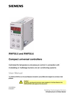
Transcription of RWF40 Compact Universal Controllers
1 Compact Universal Controllers optimized for temperature and pressure control in connection with modulating or multistage burners User Manual The controller and this User Manual are intended for use by OEMs which integrate the controller into their products! CC1B7865en Siemens Building TechnologiesHVAC Products2/57 CC1B7865en HVAC Products HVAC Products CC1B7865en 3/57 Introduction .. 6 General 6 Description ..6 Typographical conventions .. 7 Warning symbols .. 7 Notification 7 7 Type of unit .. 8 Type field .. 8 Installation .. 9 Installation site and climatic conditions .. 9 Dimensions .. 9 Side-by-side mounting .. 10 Mounting in a panel cutout .. 10 Cleaning the front .. 11 Removing the controller 11 Electrical connections.
2 12 Installation notes .. 12 Block diagram .. 13 Assignment of 14 Galvanic 17 Operating 18 Low-fire operation .. 18 High-fire 18 Modulating burner, floating output .. 18 Modulating burner, analog output .. 19 2-stage burner, floating 19 2-stage burner, analog 20 Safety shutdown .. 20 Predefined setpoint .. 20 Setpoint changeover SP1 / SP2 , analog setpoint shift .. 21 Setpoint changeover SP1 / external 22 Setpoint SP1 , analog / binary setpoint shift .. 23 External setpoint, binary setpoint shift .. 24 Weather-dependent setpoint shift .. 25 Heating curve slope .. 26 Response threshold Q .. 27 Cold start of plant .. 28 Contents 1. 2. 3. 4. 5. 4/57 CC1B7865en HVAC Products Operation.
3 29 Basic display .. 30 Meaning of the display and buttons .. 30 User level ..31 Changing the setpoints .. 31 Manual operation of a modulating burner .. 33 Manual operation of a 2-stage burner .. 33 Start self-setting .. 34 Display of the software version and of unit of actual value .. 34 Parameter 35 Entering 35 Configuration 35 Changing the configuration code .. 35 Parameter settings .. 36 Configuration .. 38 C111 inputs .. 38 C112 limit comparator, controller type, setpoint SP1 , 40 C113 unit address, dimensional unit, 44 SCL scaling of standard signal range start, analog input 45 SCH scaling of standard signal range end, analog input 45 SCL2 scaling of standard signal range start, analog input 45 SCH2 scaling of standard signal range end, analog input 46 SPL lower setpoint limit .. 46 SPH upper setpoint limit .. 46 OFF1 actual value correction for analog input 1 .. 46 OFF2 actual value correction for analog input 2 .. 46 OFF3 actual value correction for analog input 3.
4 46 dF1 2nd order digital filter for analog input 46 dF3 1st order digital filter for analog input 3 (only with ).. 46 oLLo lower working range limit (only with ) .. 47 oLHi upper working range limit (only with ).. 47 dtt bus watchdog timer for remote operation (only with ) .. 47 Self-setting function .. 48 Self-setting function in high-fire operation .. 48 Checking the controller 50 What to do .. 51 ..numbers are flashing on the 51 6. 7. 8. 9. 10. HVAC Products CC1B7865en 5/57 Technical data .. 52 Inputs .. 52 Analog input 1 (actual value) .. 52 Analog input 2 (external setpoint, setpoint shift).. 52 Analog input 3 (outside temperature) .. 53 Binary input D1 .. 53 Binary input D2 .. 53 Outputs .. 53 Output 1 (release of burner) .. 53 Output 2, 3 (floating output) .. 53 Output 4 (limit comparator) .. 53 Output 5, analog output (option) .. 54 Transducer supply .. 54 Interface RS-485 (optional).
5 54 General ratings .. 54 Measuring 55 Monitoring of measuring 55 Environmental 55 Current 56 Process data .. 56 Parameter level .. 56 Configuration level .. 57 11. 12. 6/57 CC1B7865en HVAC Products 1. Introduction Please read this User Manual before switching on the controller . Keep the User Manual in a safe place which can be accessed by all users at all times. Please help us improve the information given in the User Manual. Your suggestions will be welcome. All necessary settings and, where required, the settings to be made inside the unit, are described in this User Manual (applicable to controller software version and ). Section Display software version and dimensional unit Should any problems arise during commissioning, do not make any unauthorized manipulations on the unit.
6 You could endanger your rights under the warranty terms! Please contact us in such a case. When returning modules, assemblies or components to HVAC Products, the regulations as per DIN EN 100 015 Protection of electrostatically sensitive devices must be observed. Always use the appropriate ESD packaging for transport. Please take note that we cannot assume liability for damage caused by ESD. ESD = electrostatic discharge The is used primarily for the control of temperature or pressure in oil- or gas-fired heating plants. It is a Compact modulating controller without position feedback acting on the burner. An external switch can be used to change it to a 2-position controller for the control of 2-stage burners. The integrated thermostat function switches the burner on and off. The thermostat (relay output 1) can be used as a thermal reset limit thermostat conforming to DIN 3440. An adjustable response threshold is used to switch to a higher burner output (high-fire operation).
7 In modulating operation, the operates as a PID controller . In 2-stage operation, the provides control based on the set switching threshold. The setpoint of the can be adjusted either on the controller itself or externally. Minimum and maximum setpoint limits can be adjusted. A self-setting function is provided as a standard feature. The plug-in controller module measures 96 x 48 x mm and is especially suited for mounting in control panels. The controller features two 4-digit 7-segment displays for the actual value (red) and the setpoint (green). A limit comparator is also provided; its switching characteristic can be set on the configuration level. A choice of 8 different limit comparator functions is available. An RS-485 interface is provided for integrating the controller into a data network. Output 5 can be used as an analog output for modulating or 2-stage operation. All connections are made via screw terminals at the rear of the unit.
8 General notes ) * Description Use Control Options HVAC Products CC1B7865en 7/57 1. Introduction The signs for Danger and Caution are used in this User Manual under the following conditions: Danger This symbol is used where there may be a danger to staff if the instructions are disregarded or not strictly observed! * Caution This symbol is used where there may be damage to equipment or data if the instructions are disregarded or not strictly observed! Caution This symbol is used if precautionary measures must be taken in handling electrostatically sensitive components. ) Note This symbol is used to draw your special attention to a remark. Reference This symbol refers to additional information in other Manuals, chapters or sections. abc . Footnote Footnotes are comments, referring to specific parts of the text. They consist of 2 parts: 1) The markings in the text are arranged as continuous superscript numbers 2) The footnote text is placed at the bottom of the page and starts with a number and a period Action This symbol indicates that a required action is described.
9 The individual steps are indicated by an asterisk, : Press the = button PGM Buttons Buttons are shown in a box. Either symbols or text are possible. If a button has multiple assignments, the text shown is always the one that corresponds to the function currently used. EXIT + = Button combi-nations The representation of buttons combined with a plus sign means that, first; the EXIT button must be kept depressed before pressing the other button. Typographical conventions Warning symbols Notification symbols Presentation 8/57 CC1B7865en HVAC Products 2. Type of unit The type field is glued onto the housing. The type designation consists of operating voltage and type reference of the unit. Type of unit Description Basic version with floating output With additional analog output With additional analog output and RS-485 interface Packaging variants * The power supply must agree with the operating voltage given on the type field.
10 The measured value range and the analog inputs are factory-set. Chapter 8 Configuration Adapter frame ARG40 for plants where the predecessor model was used (for conversion to ). Bracket ARG41 for mounting the on 35 mm DIN rails conforming to DIN 46277. Dummy cover for covering control panel cutouts for the Type field Location Types Factory setting Accessories HVAC Products CC1B7865en 9/57 3. Installation The installation site should be free from vibrations, dust and corrosive media The controller should be installed away from sources of electromagnetic fields, such as variable speed drives or high-voltage ignition transformers Relative humidity: < 95 % (noncondensing) Ambient temperature range: +50 C Storage temperature range: +70 C 489691,5K6 PGMEXITRWF40112 Panel cut-out to DIN 43 7004592+0,6+0,843,5127,515,57865m01e/120 0 Installation site and climatic conditions Dimensions 10/57 CC1B7865en HVAC Products 3.