Transcription of S-311-S-819 - Resistor, Fixed, Foil (Managanin) Power ...
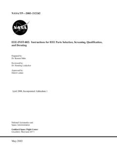
1 REVISIONS SYMBOL DESCRIPTION DATE APPROVAL A Rev~s~\ r4" KN 1\-\\5 10/'=./q7 I~ SHEET REVISION STATUS SH 1 2 3 4 5 6 7 8 9 10 11 12 13 14 15 16 17 18 19 20 REV A A A A A A A A A A A SH 21 22 23 24 25 26 27 28 29 30 31 32 33 34 35 36 37 38 39 40 REV ORIGINATOR: ~dy~ DATE FSC:S90S Antonio Reyes/Fairchild 7;;(2/;7 APPROVED: I,. / , Jay Brusse/Unisys ({It a . {Juvwc q (Jo/, 1 resistor , Fixed, Foil CODE 311 APPROVAL: (Manganin) Power , Michael Sampson 11/d~~~ Current Sensing, IO/'tJ/37 Surface mount CODE 311 SUPERVISORY APPROV~: I I I Ronald Chinnapongse ~~ Ir~7 ADDITIONAL APPROVAL: Karen Castell S-311-S-819 NATIONAL AERONAUTICS AND SPACE ADMINISTRATION GODDARD SPACE FLIGHT CENTER GREENBELT, MARYLAND 20771 CAGE CODE: 25306 Page 1 of 11 1. SCOPE 1 .1 S<?)))}}
2 Ope ~h!s specification c~)Vers t~e s~reening requirements for a fixed, manganin fOil, precIsion, current sensing resistor In a surface mounted package. This 4-terminal (two Power J-shaped and two sense gull-wing-shaped) resistor is intended for use in space flight hardware by the NASA Goddard Space Flight Center/MIDEX project. Goddard part number. Parts screened to this specification shall be identified by a Goddard part number of the following form. G311S819 Goddard Designator (See ) -1 ROOO Resistance Value (See ) :.1 Tolerance (See ) Goddard designator. The designator denotes resistors as specified in Figure 1, Table 1 and Table 2 and herein. 1 .4 Resistance value. The nominal resistance value in ohms is specified by five characters. The letter R is used to signify the decimal point as in the following examples: examples: 1 ROOO = Q R0033 = mQ The resistance value may be any value within the resistance range listed in Table 1.
3 Resistance tolerance. The resistance tolerance is identified by a dash number in accordance with Table 2. 2. APPLICABLE DOCUMENTS Documents. The following documents, of the issue in effect on the date of invitation for bids or request for proposal, form a part of this specification to the extent specified herein. STANDARDS MIL-STD-202 MIL-STD-883 Test Methods for Electronic and Electrical Component Parts Test Methods and Procedures for Microelectronics Order of precedence. In the event of any conflict between the text of this specification and the references cited herein, the text of this specification shall take precedence. However, nothing in this text shall supersede applicable laws and regulations unless a specific exemption has been obtained.
4 Copies of documents. Copies of federal and military documents can be obtained from the procuring activity. IS-311-S-819 Page 2 of 11 REV A 3. REQUIREMENTS Devices supplied to this specification shall meet the screening and qualification requirements specified herein. Design and construction. Resistors shall be of the design and construction and dimensions depicted in Figure 1. The construction is based on an etched manganin foil resistor element laminated to an aluminum or copper base with an electrically isolating but thermally conductive adhesive. The manganin foil is connected to four massive copper terminals and encapsulated in a plastic package. Package outline. This device shall conform to the package outline shown in figure 1. Pin-out configuration.
5 The pin-out configuration for the device is as shown in figure 1. Electrical Periormance Characteristics. The electrical periormance characteristics, shall be as specified in Table 1 herein and shall apply over the full operating temperature range. Operating temperature range. The operating temperature range is -55 C to 125 C ambient. Power rating. The Power rating is based on continuous full load operation, not exceeding the maximum working current in free air at a rated ambient temperature of +25 C (see Table 1). For higher temperatures, derating shall be in accordance with Figure 2. Figure 1. Package Outline. All dimensions are shown in millimeters IS-311-S-819 Page 3 of 11 IE sa )1 rli1 +JH~ --l'~ E1, E2 = Sense Terminals = Power Terminals REV A IS-311-S-819 Table 1.
6 Specification Parameters Resistance Range Temperature Coefficient of Resistance (20 C to 60 C) Power Rating Dielectric Withstanding Voltage Inductance Thermal Resistance to Ambiance Range 1 mQ to Q 3W 1000 VAC < 10 nH Rth < 30 CIW Stability (P = 0 W, T A = 125 C) after 2000 hrs Deviation < Operating Temperature Range -55 C to 125 C Table 2. Resistance Tolerance Resistance Tolerance Dash Number -1 Figure 2. Derating "-~ lOa 0 D-75 i I a: 50 '0 C 25 ~ Q) J J I D-O 20 40 60 80 100 120 Terminal Temperature (OC) Page 4 of 11 REV A Voltage rating. Each resistor shall have a rated direct current (dc) continuous working voltage, or an approximate sine wave root-mean-square (rms) continuous working voltage at commercial line frequency and waveform, corresponding to the Power rating as determined from the following formula: E = -vPR, where: E = rated dc or rms continuous working voltage P = Power rating (see ) R = nominal resistance (see Table 1) DC resistance.
7 When resistors are tested as specified in , the DC resistance shall be within the specified tolerance of the nominal resistance. Thermal shock. When resistors are tested as specified in , there shall be no evidence of mechanical damage, and the change in resistance shall not exceed Temperature characteristic of resistance (TeR). When resistors are tested as specified in , the resistance temperature characteristic shall meet the requirement of Table 1. Resistance to soldering heat. When resistors are tested as specified in , there shall be no evidence of mechanical damage, and the change in resistance shall not exceed Solderability. When resistors are tested as specified in , the criteria for wire-lead terminal evaluation that is contained in the referenced test method shall be met.
8 High temperature storage. When resistors are tested as specified in , there shall be no evidence of mechanical damage, and the change in resistance shall not exceed (0 to 1000 hours). Life (-1 ROOO only). When resistors are tested as specified in , there shall be no evidence of mechanical damage, and the change in resistance shall not exceed (0 to 1000 hours). marking . The resistors which successfully complete all test and inspection, as defined by the Goddard part number and the applicable tables herein, shall be permanently marked with the Goddard part number in accordance with the following: a. marking shall in no way interfere with or obscure any of the original manufacturer's marking . b. The number of lines shall be at discretion of the test facility or laboratory.
9 C. marking shall be placed in such a manner to afford the most ready identification when the device is installed in its normal mounting configuration. When space limitation prohibit the marking of the full Goddard part number as specified in , resistors shall then be individually packaged in suitable conductive bag(s) or container(s) for ESD control. The individual package shall display the full marking and shall include as a minimum: IS-311-S-819 Page 5 of 11 REV A a. The complete Goddard part number as specified in b. Manufacturer's identification. c. Seal date code or inspection identification. Data requirements. Attribute data resulting from screening test (see ) shall be traceable to each lot of resistors and lot date code and shall accompany each shipment of resistors delivered to Goddard.
10 Resistors which have passed the screening test may be delivered prior to the completion of QCI testing (see ), with prior approval by Goddard. Certification of conformance. A certification of conformance in accordance with this specification shall be provided with each lot of resistors. 4. QUALITY ASSURANCE PROVISIONS Responsibility for inspection. The test facility is responsible for the performance of all inspection requirements, as specified herein, using his own or any other suitable facility acceptable to Goddard. Upon receipt of product, Goddard reserves the right to perform any of the inspections set forth in the specification where such inspections are deemed necessary to verify conformance to prescribed requirements. Classification of inspection.