Transcription of S11 VF- TM TOSVERT
1 TOSVERT VF-S11E6581157 1 I 2 3 4 VF-S11 5 6 7 8 9 (x) 1010 1111 1212 1313 1414 1515 1616 TOSVERTTM VF-S11 200V 200V 15kW 400V 15kW (x) 1 AdditionalAdditionalAdditionalAdditional sheetsheetsheetsheet The VF-S11 models that conform to the UL Standard and CSA Standard have the UL/CSA mark on the nameplate.
2 This additional sheet is correction and additional information for Appendix of E6581157. 1. General The following steps must be performed before wiring and servicing. (1)Turn off all input power. (2)Wait at least ten minutes and check to make sure that the charge lamp is no longer lit. (3)Use a tester that can measure DC voltage (800 VDC or more), and check to make sure that the voltage to the DC main circuits (across PA/+ and PC/-) is 45V or less. If these steps are not properly performed, the wiring will cause electric shock. 2. Compliance with Installation The VF-S11 inverter must be installed in a panel, and used within the ambient temperature specification.
3 Standard installation 5 cm or more 5 cm or more 10 cm or more 10 cm or more VF-S11 In case of and over drive motor, please use the minimum 30 by 30 by 12 inch enclosure. Environments Use environments Indoor, altitude: 1000m (Max.), not exposed to direct sunlight, corrosive gas, explosive gas or vibration (less than ) (10 to 55Hz) Ambient temperature -10 to 40 C Maximum Surrounding Air Temperature 40 C Storage temperature -25 to +70 C Relative humidity 20 to 93% (free from condensation and vapor). Current reduction According to the carrier frequency f300 setting, you may need to reduce the inverter s continuous output current.
4 Reduction rates vary depending on the capacity of the inverter. [Single-phase/Three-phase 200V class ] VFS11S- VFS11- Input voltage 200V ~ 240V PWM carrier frequency ~ ~ 2002PL/PM A A 2004PL/PM A A 2007PL/PM A A 2015PL/PM A A 2022PL/PM A A 2037PM A A 2055PM A A 2075PM A A 2110PM A A 2150PM A A [Three-phase 400V class ] VFS11- Input voltage 380V ~ 480V Input voltage 480V ~ 500V PWM carrier frequency PWM carrier frequency ~ ~ ~ ~ 4004PL A A A A 4007PL A A A A 4015PL A A A A 4022PL A A A A 4037PL A A A A 4055PL A A A A 4075PL A A A A 4110PL A A A A 4150PL A A A A 2 3.
5 Compliance with Connection Use the UL conformed cables (Rating 75 C or more, Use the copper conductors only.) to the main circuit terminals (R/L1, S/L2, T/L3, U/T1, V/T2, W/T3). ->For recommended tightening torque for the main terminal, see Table 1. -> For recommended wire size for the main terminal, see Table 2. ->Use the electric wire of class 1 for the control wire. (For wire size and tightening torque, see the label on unit) For instruction in the United States, Integral solid state short circuit protection does not provide branch circuit protection. Branch circuit protection must be provided in accordance with the National Electrical Code and any additional local codes.
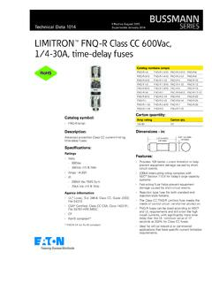
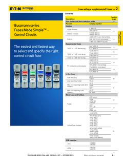
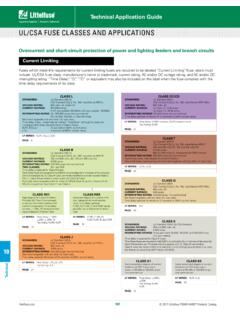
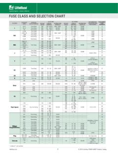
6 For instruction in the Canada, Integral solid state short circuit protection does not provide branch circuit protection. Branch circuit protection must be provided in accordance with the Canadian Electrical Code and any additional local codes. Use the UL listed fuses at connecting to power supply. Short circuit test is performed under the condition of the power supply short-circuit currents in below. These interrupting capacities and fuse rating currents depend on the drive motor capacities. Table 1 Tighten the screws to specified torque Screw size tightening torque screw in M4 screw in M4 screw (Enclose type input terminal) 15lb in M5 screw in M6 screw in Enclose type is VFS11-xxxxPME.
7 Table 2 AIC, fuse and Wire sizes Voltage class Capacity of applicable motor (kW) Inverter model AIC (A) (Interrupting capacity) fuse class and current (A) Wire sizes of power circuit Single-phase 200V class VFS11S-2002PL AIC 1000A CC/J 6A max. AWG 14 VFS11S-2004PL AIC 1000A CC/J 10A max. AWG 14 VFS11S-2007PL AIC 1000A CC/J 15A max. AWG 14 VFS11S-2015PL AIC 1000A CC/J 20A max. AWG 12 VFS11S-2022PL AIC 1000A CC/J 30A max. AWG 10 Three-phase 200V class VFS11-2002PM/PME AIC 5000A CC/J 3A max. AWG 14 VFS11-2004PM/PME AIC 5000A CC/J 6A max. AWG 14 VFS11-2007PM/PME AIC 5000A CC/J 10A max.
8 AWG 14 VFS11-2015PM/PME AIC 5000A CC/J 15A max. AWG 14 VFS11-2022PM/PME AIC 5000A CC/J 20A max. AWG 12 VFS11-2037PM/PME AIC 5000A J 35A max. AWG 10 VFS11-2055PM AIC 22000A J 50A max. AWG 8 VFS11-2075PM AIC 22000A J 60A max. AWG 6 11 VFS11-2110PM AIC 22000A J 80A max. AWG 4(*1) 15 VFS11-2150PM AIC 22000A J 110A max. AWG 6x2 Three-phase 400V class VFS11-4004PL AIC 5000A CC/J 3A max. AWG 14 VFS11-4007PL AIC 5000A CC/J 6A max. AWG 14 VFS11-4015PL AIC 5000A CC/J 10A max. AWG 14 VFS11-4022PL AIC 5000A CC/J 15A max. AWG 14 VFS11-4037PL AIC 5000A CC/J 20A max.
9 AWG 12 VFS11-4055PL AIC 22000A CC/J 30A max. AWG 10 VFS11-4075PL AIC 22000A J 35A max. AWG 8 11 VFS11-4110PL AIC 22000A J 50A max. AWG 8 15 VFS11-4150PL AIC 22000A J 70A max. AWG 6 (*1)Use the ring terminal (Recommended the ring terminal is R22-6 [JIS standard]) 3 Table 3 Power supply short-circuit current and maximum input voltage. Input voltage Drive motor Power supply short-circuit and maximum input voltage Single-phase 200V class Up to Suitable For Use On A Circuit Capable Of Delivering Not More Than 1,000A rms Symmetrical Amperes, 240 Volts Maximum When Protected by CC/J class Fuses.
10 Three-phase 200V class Up to Suitable For Use On A Circuit Capable Of Delivering Not More Than 5,000A rms Symmetrical Amperes, 240 Volts Maximum When Protected by CC/J class Fuses. Suitable For Use On A Circuit Capable Of Delivering Not More Than 5,000A rms Symmetrical Amperes, 240 Volts Maximum When Protected by J class Fuses. and over Suitable For Use On A Circuit Capable Of Delivering Not More Than 22,000A rms Symmetrical Amperes, 240 Volts Maximum When Protected by J class Fuses. Three-phase 400V class Up to Suitable For Use On A Circuit Capable Of Delivering Not More Than 5,000A rms Symmetrical Amperes, 500 Volts Maximum When Protected by CC/J class Fuses.