Transcription of Safety manual for Fisher FIELDVUE DVC6200 SIS …
1 manual for Fisher FIELDVUE DVC6200 SIS digital Valve controller , Position Monitor,and LCP200 Local Control PanelThis supplement applies toInstrument LevelSISD evice Type130aDevice Revision1 & 2 Hardware Revision2 Firmware Revision4, 5, 6, & 7 DD Revision3, 4, & Safety manual provides information necessary to design, install, verify and maintain a SafetyInstrumented Function (SIF) utilizing the Fisher DVC6200 SIS digital valve controller . The DVC6200 SIS can be installed with a local control panel (LCP200). This document must be thoroughlyreviewed and implemented as part of the Safety lifecycle. This information is necessary formeeting the IEC 61508 or IEC 61511 functional Safety standards. WARNINGThis instruction manual supplement is not intended to be used as a stand-alone document. It must be used in conjunctionwith the following documents: Fisher DVC6200 Series Quick Start Guide (D103556X012) Fisher DVC6200 SIS Instruction manual (D103557X012) Fisher LCP200 Instruction manual (D104296X012)Failure to use this instruction manual supplement in conjunction with the above referenced documents could result inpersonal injury or property damage.
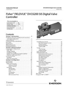
2 If you have any questions regarding these instructions or need assistance in obtainingany of these documents, contact your Emerson sales office or Local Business manual SupplementD103601X012 DVC6200 SIS digital Valve ControllerMarch 2018 Instruction manual SupplementD103601X012 DVC6200 SIS digital Valve ControllerMarch of the DeviceThe Fisher DVC6200 SIS digital valve controller is an instrument which delivers controlledpneumatic pressure to modulate a valve actuator in response to an electrical signal. An optionalvalve position monitor will either transmit a 4 20 mA signal in response to the actual valve travel oropen and close a discrete limit switch based on a configurable trip point. An LCP200 can be used inconjunction with of the DVC6200 SIS to locally open and close a Safety shutdown valve as well asinitiating a partial stroke Safety manual applies to the DVC6200 SIS instrument with electronics hardware revision 2(HW2)
3 And firmware revision 4, 5, 6, and 7 with the following product mA24 VDCR elay ARelay BRelay CPositionMonitorDVC6200 SISI ntegral, Aluminum DVC6200S SISI ntegral, Stainless Steel DVC6205 SISDVC6215 Remote Mount,Aluminum APPLICATIONDETT ETT 4-20 mA 24 VDC AccessoriesLCP100/LCP200 Local Control Panel, HART OnlyLC340 Line Conditioner, 24 VDCI nstruction manual SupplementD103601X012 DVC6200 SIS digital Valve ControllerMarch , Abbreviations, and Acronyms Beta factor for common cause effects of failureDDDevice Description, an electronic data file that describes specific features and functions of adevice to be used by host energize to TripDTMD evice driver that provides a unified structure for accessing device parameters, configuring andoperating the devices, and diagnosing SISD igital Valve controller , product model designation for Safety Instrumented System applicationsESDE mergency Shut DownETTE nergize to TripFITF ailure In Time (1x10 9 failures per hour)FMEDAF ailure Mode Effect and Diagnostic AnalysisHARTH ighway Addressable Remote Transducer, open protocol for digital communicationsuperimposed over a direct Fault Tolerance Failure rate.
4 DD: dangerous detected; DU: dangerous undetected; SD: safe detected; SU: Conditioner; product model designation for a device that is inserted in the loop when theinstrument (in Multidrop Mode) is powered with a low impedance 24 V source, to enable Control Panel; product model designation for a device that can be connected to a DVC6200 SIS instrument to enable manually initiated DemandModeMode of operation of a Safety instrumented function where the demand interval is greater thantwice the proof test mode of the DVC6200 SIS where the instrument controls the current drawn to enableit to be powered with 24 Probability of Failure on DemandPoint to PointOperating mode of the DVC6200 SIS whereby the instrument is powered with 4 20 Valve Stroke TestRelay APneumatic booster relay for double or single acting applications. Typical construction for doubleacting DETT BPneumatic booster relay for single acting reverse applications.
5 Typical construction for singleacting ETT CPneumatic booster relay for single acting direct applications. Typical construction for singleacting DETT from unacceptable risk of of a device or combination of devices intended to be used within a Safety InstrumentedSystem to reduce the probability of a specific hazardous event to an acceptable Failure FractionSIFS afety Instrumented FunctionSILS afety Integrity LevelSISS afety Instrumented SystemType AElement Non Complex element (using discrete components); for details see of IEC 61508 BElement Complex element (using complex components such as micro controllers or programmablelogic); for details see of IEC 61508 manual SupplementD103601X012 DVC6200 SIS digital Valve ControllerMarch LiteratureD Fisher DVC6200 Series Quick Start Guide (D103556X012)D Fisher DVC6200 SIS Instruction manual (D103557X012)D : DVC6200 SIS, Fisher DVC6200 SIS Product Bulletin (D103555X012)D HART Field Device Specification for Fisher DVC6200 SIS (D103638X012)D Fisher LCP200 Local Control Panel Instruction manual (D104296X012)D :LCP200, Fisher LCP200 Local Control Panel Product Bulletin (D104313X012)D IEC 61508: 2010 Functional Safety of electrical/electronic/programmable electronicsafety related systemsD ANSI/ISA 2004 (IEC 61511 Mod.)
6 Functional Safety Safety Instrumented Systems forthe Process Industry SectorD Exida FMEDA Report for Fisher DVC6200 SIS, Position Monitor Applications Report No. EFC 12/02 027 R001D Exida FMEDA Report for Fisher DVC6200 SIS, DETT and ETT Applications Report No. EFC 12-02-027 R004 V3 R0 Instruction manual SupplementD103601X012 DVC6200 SIS digital Valve ControllerMarch Requirements WARNINGTo ensure safe and proper functioning of equipment, users of this document must carefully read allinstructions, warnings, and cautions in this Safety manual and the Quick Start Refer to the Fisher DVC6200 SIS Quick Start Guide (D103556X012) for mounting If a LCP200 is used, refer to the Fisher LCP200 instruction manual (D104296X012) for wiringconfigurations and Tools needed:D DVC6200 SISD Flat Head Screwdriver, 3 mm Thin Blade (wiring terminations)D Phillips ScrewdriverD 3/8 Hex Key (terminal box conduit plug)D 6 mm Hex Key (module base screws)D 5 mm Hex Key (terminal box screw)D mm Hex Key (I/P converter screws)D mm Hex Key (terminal box cover screw)D LCP200D Phillips Screwdriver (ground screw)D Flat Head Screwdriver, 3 mm Thin Blade (wiring terminations)D 10 mm Hex Key (cable entry plug)D 4 mm Hex Key (terminal cover screw)D mm Hex Key (LED module screw, front panel screw)D Torque wrench capable of 2 - N m (18 - 22 lb in) (terminal cover screw)
7 D Personnel performing maintenance and testing on the DVC6200 SIS and LCP200 shall becompetent to do manual SupplementD103601X012 DVC6200 SIS digital Valve ControllerMarch Instrumented System DesignWhen using the DVC6200 SIS digital valve controller or DVC6200 SIS with the LCP200 in a safetyinstrumented system, the following items must be reviewed and SIL Safety Failure Application Environmental Application of the Switch Output for Diagnostic SIL CapabilityD Systematic IntegritySIL 3 Capable the digital valve controller has met manufacturer design processrequirements of IEC 61508 Safety Integrity Level Random IntegrityD The digital valve controller is classified as a Type A device according to IEC 61508. Thecomplete final element subsystem will need to be evaluated to determine the SFF. If theSFF of the subsystem is >90%, and the PFDavg < 10 3, the design can meet SIL 3 @ HFT= The position monitor is classified as a Type B device according to IEC 61508.
8 Thecomplete final element subsystem will need to be evaluated to determine the SFF. If theSFF of the subsystem is >90%, and the PFDavg < 10 2, the design can meet SIL 2 @ HFT= the SFF of the subsystem is between 60% and 90%, and the PFDavg < 10 1, the designcan meet SIL 1 @ HFT= The LCP200 is classified as a Type B device per IEC61508. If the SFF of the relay outputstate change subsystem is >90% and the PFDavg < 10 2, the design can meet SIL2 @ HFT =0. If the SFF of the subsystem is between 60% and 90%, and the PFDavg < 10 1, the designcan meet SIL 1 @ HFT= manual SupplementD103601X012 DVC6200 SIS digital Valve ControllerMarch Safety FunctionD De energize to Trip Application: The application of the digital valve controller is limited for SISto low demand mode. Table 1 describes the normal and safe states of DVC6200 SIS for a DETT configuration. The digital valve controller may be operated with one of the following controlsignals:D 0 24 VDC: Normal operation is with a 24 VDC signal applied to the digital valvecontroller.
9 A shut down command is issued by interrupting the loop or taking thevoltage signal to 1 VDC or 4 20 mA: Normal operation is with a 20 mA current loop signal to the digital valvecontroller. A shut down command is issued by taking the current signal to 4 mA(nominal). If a loop powered LCP100/LCP200 is attached, the shut down command isissued by taking the current signal to 8 mA (nominal).Table 1. Normal and Safe States for De-Energize to Trip (DETT) ApplicationActionRelayInput Voltage orCurrentNormal StateSafe StateSingleC or A0 VDC or 4 mAPort A < 1 psi24 VDC or 20 mAPort A 95% of SupplyDoubleA0 VDC or 4 mAPort A pressure Port B pressure24 VDC or 20 mAPort A 95% of SupplyPort B < 1 psiD Energize to Trip Application (a less common application): The application of the digital valvecontroller is limited for SIS to low demand mode. Normal operation is with a 4 mA currentloop signal to the digital valve controller .
10 If a loop powered LCP100/LCP200 is attached,normal operation is with an 8 mA (nominal) current loop signal to the digital valve 2 describes the normal and safe states of DVC6200 SIS for an ETT configuration. Ashut down command is issued by taking the current signal to 20 mA (nominal).Table 2. Normal and Safe States for Energize to Trip (ETT) ApplicationActionRelayInput CurrentNormal StateSafe StateSingleB4 mAPort B 95% of Supply20 mAPort B < 1 psiDoubleA4 mAPort A < 1 psiPort B 95% of Supply20 mAPort A Port B pressureD Position Monitor Application: The Safety function of the position transmitter output is totransmit a 4 20 mA analog signal that represents valve position. The Safety function of thelimit switch output is to transmit a discrete signal that represents a user configurablethreshold of valve position. Table 3 describes the normal and alarm states of the PositionMonitor function of the DVC6200 manual SupplementD103601X012 DVC6200 SIS digital Valve ControllerMarch 20188 Table 3.