Transcription of Safety Products 1 July 2001 Cable-Pull Switches
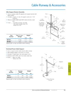
1 1 july 2001 Cable-Pull Switches Contents Overview .. 1 Model Selection, Switches .. 4 Model Selection, Accessories .. 6 Specifications .. 6 Dimensions .. 7 Cutler-Hammer Cable-Pull Switches are designed as emergency stop devices that operate when the attached cable is pulled or pushed. Also referred to as rope- pull Switches , this family offers a variety of switch sizes to fit easily into any application. Both latching and non-latching Switches are available to meet your specific requirements. Latching Switches provide a palm button or pull -chain reset depending upon the model selected. Units pro-vide maximum cable lengths, under ideal conditions, from 20 feet (6m) in one direction suitable for smaller machines, up to 245 feet (75m) in two directions 490 feet (150m) total. These long range types are ideal for conveyor installation. Ratings and Approvals UL Listed CSA Certified IEC 947-5-1 AC 15/DC 13 EN 418 DIN VDE 0660 T200 Direct opening contacts For the most current information on this product, visit our web site at: Safety ProductsCable- pull Switches Reliable Cable-Pull Switches for ON/OFF and Emergency Stop Machine Control Product Features Positive opening contacts have long operational life 1,000,000 switching actions Galvanically isolated contacts Latching operation on emergency stop models ensure machine will not restart until the switch is manually reset Metal housings provide long life in rough industrial environments Long cable span lengths reduce the number of Switches required per application A full selection of installation hardware is available The Cable-Pull System A Cable-Pull System, also referred to as Rope- pull , is designed to provide an emer-gency stop function as part of a larger Safety control circuit.
2 A typical system, shown in Figure 1, consists of a Safety rated switch, a cable , a turnbuckle and often times a spring and cable supports. The cable is installed horizontally along a zone of a machine where a point of possible hazard exists. The cable is installed with ten-sion on it so that the switch has the ability to monitor when the cable is slack or bro-ken, in addition to monitoring when the cable is pulled. Also, for Safety use, the switch must latch in the emergency stop position and be manually 1. Typical Cable-Pull System CableSwitchTightening TurnbuckleEye Bolt and NutThimbleCable Clamp4-6 inches (100-150 mm)Eye Bolt For Customer Service in the call 1-800-356-1243, in Canada call 1-800-268-3578. For Application Assistance in the and Canadacall 1-800-426-9184. E48 Cable-Pull Switches are only intended for operation as a component of an overall Safety control circuit. 2 2001 Careful consideration should be taken when designing a system so that the switch is easily pulled at critical sec-tions of the cable run.
3 The nature of the system is such that there will be certain zones of the cable run where the sensor may or may not operate when the cable is pulled (unknown action). Examples of these zones are very near the ends of the cable or near eyebolt supports. Steps should be taken to minimize the friction of the cable move-ment. These include using pulleys in place of eyebolt sup-ports, and minimizing or eliminating turns in the cable (the ideal run has no turns). Switch Construction and Operation Cable-Pull Switches come in three distinct types: Basic Switches These Switches are merely momentary actuated Switches . They are not suitable for use in Safety applications. The contact switching mode is referred to as break before make, which means the first set of con-tacts break before the second set makes. Break before make contact configurations are shown non-overlapping configuration does not allow for monitoring the cable status. This switch is used where the cable is not installed under tension.
4 As this switch is not recommended for Safety applications, Cutler-Hammer does not include it in its offering. Overlapping Contacts, Non-latching Switches Unlike the basic switch, overlapping contact Switches carry contacts that make before break. These contacts allow cable status monitoring. As seen above right, when the contacts are wired in series, indication of cable status can be determined electrically. The risk in using this non-latching switch is that if the cable is pulled, then released, the action that was stopped by pulling the cable could possibly be restarted. Figure 3. Contact position based on cable status Safety Rated Latching Switches This is the only type of switch recommended for Safety applications. In addition to the features mentioned above, these Switches also latch when the contacts are actuated. This requires a deliberate action to reset the contacts and thus restart the machine where the hazard existed. Reset can happen by pressing or pulling an operator located on the switch or by requiring a key to release the switch (once an emergency stop has occurred, manual, deliberate reset is required).
5 All Cable-Pull Switches offer positive-mode operated gal-vanically isolated contacts as required by IEC 947-5-1. In applications where the cable is set up under tension, the normally open contacts are held closed while the normally closed contacts remain closed. When the cable goes slack, the normally open contacts (held closed) will open. When the cable is pulled, both sets of contacts open. This is described in Figure 3. Wiring the contacts in series will give indication of cable actuation in either the case of overlapping contacts, the travel of overlap is described in the contact configuration drawing (see Figure 4). It is important that the cable travel under nor-mal operating conditions does not exceed this distance to avoid nuisance tripping. Expansion of the cable under varying ambient temperatures can also be a cause of nui-sance tripping. An explanation of this effect is described in the next section. Safety ProductsCable- pull (3) (5)050inch(mm) (1)Figure 2. Non-overlapping contact actuation points in thenormal stand-bymode.
6 Normally opencontacts are heldclosed to monitorcable slack in thecable-pulled closedcontacts are in thecable-broken opencontacts return tothe normally open state. 3 july 2001 cable Considerations The cable is the actual interface with the user, it is plastic coated and is typically less than 4 mm in diameter. The cable is installed between the switch and the support at the opposing end. It is important that the support for the cable be sturdy enough to handle the force required to operate the effects on the cable are important to note when configuring a system that has long cable runs (greater than 18 meters). The expansion and contraction properties of the cable are referred to as its Coefficient of Linear Expansion (K). Coefficient of Linear Expansion (K) = x 10 -6 inches per degree F per inch ( mm per degree C per meter) Since contact overlap is critical in the switch operation, the expansion of the cable can be a source of nuisance tripping in installations where the ambient temperature changes greatly.
7 Let s look at an example:A conveyor in the shipping area of a food processing plant has maximum temperature fluctuations of 20 C. The cable run on the conveyor is 20 meters. Our Data: K = mm / degree C / mT differential = 20 degrees CL cable = 20mExpected cable expansion = x 20 x 20 = mmBased on this result, it is vital that the overlap in the switch contacts is greater than mm. Linear expansion is usually not a factor in applications where the cable run is not long and the ambient temperature does not fluctu-ate more than 10 consideration of the cable is that when pulled with great force, the cable can initially expand or stretch and affect system setup. It is usually recommended that the cable be forcefully pulled prior to tuning the cable tension with the turnbuckle. This will expose areas in the system that will initially stretch or expand. Adjustments can then be made to take up the added slack. Safety ProductsCable- pull (11) (13)050inch(mm) (2) ( )Latch: ( )Figure 4.
8 Overlapping contact configuration, the overlapping gap is measured as 9 mm 4 2001 Safety ProductsCable- pull Switches 13142526 ( ) (5)040inch(mm) ( ) (4) ( ) (5)050inch(mm) ( ) ( ) ( ) ( )050inch(mm) ( ) (4)Latch: ( ) (4) (6)090inch(mm) (2) ( ) (4) (6)090inch(mm) (2) ( )Latch: ( ) ( ) (7)0150inch(mm) ( ) ( ) 13142526 13142526 13142526 13142526 13142526 CLOSED OPENON/OFF Switching only not for human Safety useON/OFF Switching only not for human Safety useON/OFF Switching only not for human Safety useON/OFF Switching only not for human Safety use Model Selection Cable-Pull Switches Non-latching models are for ON/OFF switching only and are not suitable for human Safety applications. ContactsContact OperationPower HandlingSwitching FrequencyCatalog Number Short Range Span Length 20 foot (6m) Span LengthPlastic BodyNon-latching AC10A50/minute maximum E48 CSP106 20 foot (6m) Span LengthMetal BodyNon-latching AC10A50/minute maximum E48 CSM106 20 foot (6m) Span LengthMetal BodyLatching AC10A17/minute maximum E48 CSM106 BMid Range Span Length 40 foot (12m) Span LengthMetal BodyNon-latching AC16A50/minute maximum E48 CSM112 40 foot (12m) Span LengthMetal BodyLatching AC16A20/minute maximum E48 CSM112B 59 foot (18m) Span LengthMetal BodyNon-latching AC16A50/minute maximum 5 july 2001 Safety ProductsCable- pull Switches 13142526 (6) ( ) (8)080inch(mm) (2)Latch: ( ) ( ) (6) ( ) (8)080inch(mm) (2)Latch: ( )33-3445-46 (11) (13)050inch(mm) (2) ( )Latch: ( ) (20) (24)0180inch(mm) (2) ( )Latch.
9 (22) 11-1223-24030 Latch11-1223-2430 25 20 12 12 25 20 LatchNormalRL 11-1223-24030 Latch11-1223-2430 25 20 12 12 25 20 LatchNormalRL 131425263334 1314252633344546 1112232423241112 1112232423241112 13142526 CLOSED OPEN Model Selection Cable-Pull Switches (Continued) Unit available with optional 24 208V AC/DC LED indicating light. To specify add LUV to end of Catalog Number. Contact factory for availability. ContactsContact OperationPower HandlingSwitching FrequencyCatalog Number Mid Range Span Length (Continued) 59 Foot (18m) Span LengthMetal BodyLatching AC16A20/minute maximum E48 CSM418B AC16A20/minute maximum E48 CSM218B 115 Foot (35m) Span LengthMetal BodyLatching AC16A20/minute maximum E48 CSM135B Long Range Span Length 230 Foot (70m) Span LengthMetal BodyLatching AC16A20/minute maximum E48 CSM170B 490 Foot (150m) Span Length(245 Foot [75m] Each Direction)Metal BodyLatching direction250V AC10A10/minute maximum E48 CSM375R 490 Foot (150m) Span Length(245 Foot [75m] Each Direction)Metal BodyLatching direction500V AC10A10/minute maximum E48 CSM375RC 6 2001 Safety ProductsCable- pull Switches Specifications Mechanical Life1 million cyclesReset MethodPushbutton (for models ending in B ).
10 pull ring (for models ending in R or RC )Protection ClassNEMA 1, 2, 3, 4, 12 (IP65)Switching , or , Forced disconnection of contactsControl Wire Size14 AWG maximum recommendedUtilization CategoryAC15, DC13 Tempera-ture Range-22 to 176 F (-30 to 80 C)Housing MaterialPlastic or cast aluminum Model Selection Accessories Quantity ordered indicates length, for example, a quantity of 5 equals five meters of cable . DescriptionSwitches Used With:Catalog Number CablePlastic coated steel cable , red color, sold in meter increments Short and Mid Range E48 CARD2 Long Range E48 CARD4 Eye Bolt and NutUsed for supporting cableAll E48 CABM8 Tightening TurnbuckleAdjusts cable system length to properly position switch contactsShort and Mid Range E48 CATM5 Long Range E48 CATM6 ThimbleUsed where cable is attached to switch, turnbuckle or at end anchor pointShort and Mid Range E48 CATD2 Long Range E48 CATD3 PulleyRecommended when a 90 turn is required for cable configurationAll E48 CAPUL cable ClampClamps cable at termination pointsShort and Mid Range E48 CACD2 Long Range E48 CACD3 Spring24N ( N/mm coefficient) ( N/mm coefficient)E48 CSM375R orE48 CSM375RC E48 CAS24 orE48 CAS18 Short and Mid Range SystemLong Range SystemCableSwitchTightening TurnbuckleEye Bolt and NutThimbleCable Clamp4-6 inches (100-150 mm)Eye BoltSpringThimblePulleySwitchCableTighte ningTurnbuckleCable Clamp4-6 inches (100-150 mm)16 feet max (5 m)