Transcription of Safety Recall P54 / NHTSA 14V-530 Fuel Pump Relay
1 Copyright 2014, Chrysler Group LLC, All Rights Reserved (wah) December 2014 Dealer Service Instructions for: Safety Recall P54 / NHTSA 14V-530 Fuel Pump Relay 2011 (WD) Dodge Durango (WK) Jeep Grand Cherokee NOTE: This Recall applies only to the above vehicles equipped with a engine (sales code ERB) or a Hemi engine (sales code EZH). IMPORTANT: Many of the vehicles within the above build period have already been inspected or repaired and, therefore, have been excluded from this Recall . The Totally Integrated Power Module (TIPM) on about 188,000 of the above vehicles contains an internal fuel pump Relay that could operate intermittently or fail without warning. An intermittent or failed fuel pump Relay could cause the engine to stall while driving and cause a crash without warning. The TIPM internal fuel pump Relay must be disabled and an external fuel pump Relay must be installed.
2 Models IMPORTANT: Some of the involved vehicles may be in dealer used vehicle inventory. Dealers should complete this Recall service on these vehicles before retail delivery. Dealers should also perform this Recall on vehicles in for service. Involved vehicles can be determined by using the VIP inquiry process. Subject Repair Safety Recall P54 Fuel Pump Relay Page 2 Part Number Description CBP4P541AB External Fuel Pump Relay Package Each package contains the following components: Quantity Description 1 Relay , Fuel Pump 1 Harness, Wiring 3 Tube, Shrink 3 Crimp, Brass 1 Pin, Push Each dealer to whom vehicles in the Recall were assigned will receive enough External Fuel Pump Relay Packages to service about 20% of those vehicles. The following special tools are required to perform this repair: 10042* Wire splice crimp tool 6680-2PA Pick, Terminal * NOTE: One wire splice crimp tool was mailed to each Chrysler/Jeep/Dodge dealer free of charge in June, 2007.
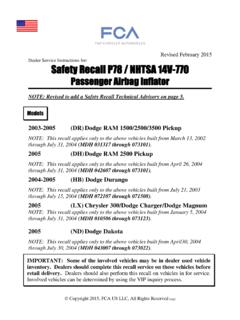
3 Additional wire splice crimp tools can be purchased, at dealer expense, by contacting Mopar Essential Tools and Service Equipment at 1-855-298-2687 or during regular business hours. Contact Mopar Essential Tools regarding issues with any tools or equipment purchased or supplied through the Mopar tool and equipment program. Parts Information Special Tools Safety Recall P54 Fuel Pump Relay Page 3 A. Inspect for External Fuel Pump Relay 1. Open hood. 2. Inspect for an external fuel pump Relay (Figure 1): If there is an external fuel pump Relay installed, no further action is required. Return the vehicle to the customer. If there is no external fuel pump Relay , continue with Section B. Install External Fuel Pump Relay . Service Procedure RIGHT FRONT SHOCK TOWER TIPM COVER RADIATOR CAP POWERTRAIN CONTROL MODULE EXTERNAL FUEL PUMP Relay HIGH FAN Relay Figure 1 Inspect for External Fuel Pump Relay Safety Recall P54 Fuel Pump Relay Page 4 B.
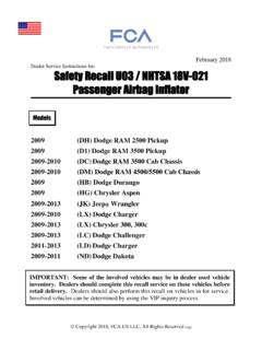
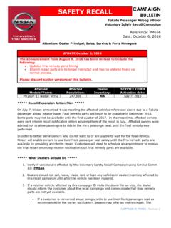
4 Install External Fuel Pump Relay 1. Position the passenger seat fully forward. 2. Open the battery access cover located under the passenger front seat and disconnect the negative battery cable (Figure 2). 3. Remove and save the Totally Integrated Power Module (TIPM) access cover. 4. Remove and save the B+ cable terminal retaining nut. 5. Carefully separate the B+ cable terminal from the B+ TIPM stud (Figure 3). Service Procedure (Continued) Figure 2 Battery Access Figure 3 B+ Cable Terminal PASSENGER SEATBACK BATTERY ACCESS COVER BATTERY B+ TIPM STUD B+ CABLE TERMINAL TIPM ASSEMBLY Safety Recall P54 Fuel Pump Relay Page 5 6. Push the four TIPM retaining tabs and separate the TIPM from the TIPM support bracket (Figure 4). 7. Unplug the 50-way electrical connector from the bottom of the TIPM (Cavity A ) (Figure 5). Service Procedure (Continued) Figure 4 TIPM Release Tabs Figure 5 TIPM 50-Way Electrical Connector TIPM RELEASE TABS TIPM ASSEMBLY TIPM ASSEMBLY 50-WAY CONNECTOR CAVITY A 40-WAY CONNECTOR 50-WAY CONNECTOR BROWN WIRE THAT WILL BE CUT AND SPLICED TO NEW Relay HARNESS Safety Recall P54 Fuel Pump Relay Page 6 8.
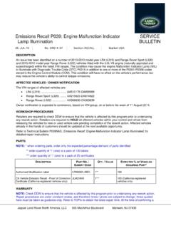
5 Locate the brown wire in cavity number 40 of the 50-way electrical connector (Figure 6). 9. Cut the brown wire one inch (25 mm) from the 50-way electrical connector (Figure 7). Service Procedure (Continued) Figure 6 Locate Brown Wire in 50-Way Connector Figure 7 Cut the Brown Wire One Inch From Connector BROWN WIRE THAT WILL BE CUT AND SPLICED TO NEW Relay HARNESS 50-WAY CONNECTOR CUT BROWN WIRE AT 50-WAY CONNECTOR 50-WAY CONNECTOR CAVITY NUMBER 40 50-WAY CONNECTOR LOCK BAR 50-WAY CONNECTOR LOCK BAR Safety Recall P54 Fuel Pump Relay Page 7 10. Install shrink tube to the connector side brown wire to insulate the wire end. This wire will no longer be used (Figure 8). 11. Using the following procedure, splice the brown wire on the wire harness to the brown wire on the new fuel pump Relay harness: a. Strip approximately inch (13 mm) of insulation from the end of the brown wire on the new fuel pump Relay wire and the original brown wire.
6 B. Place a piece of black shrink tube, provided in the repair kit, over the cut brown wire. c. Using the supplied brass splice band clamp and crimp tool 10042, crimp the brown wire that had the insulation stripped on the wire harness side to the matching brown wire on the new fuel pump Relay harness (Figure 9). d. Solder the brass splice band clamp with rosin core solder. e. Slide the shrink tube evenly over the soldered brass splice and apply heat to the shrink tube until glue comes out of both ends of the shrink tube. 12. Carefully plug the 50-way electrical connector into the bottom of the TIPM. CAUTION: Be sure that the 50-way connector lock bar is fully engaged. Service Procedure (Continued) Figure 8 Insulate Brown Abandoned Wire Figure 9 Crimp and Solder Brown Wires PLACE SHRINK TUBE OVER ABANDONED BROWN WIRE BROWN WIRE THAT WILL BE SPLICED TO NEW FUEL PUMP Relay WIRE HARNESS 50-WAY CONNECTOR BROWN WIRE FROM NEW FUEL PUMP Relay WIRE HARNESS CRIMP TOOL 10042 BRASS SPLICE BAND CLAMP BROWN WIRE 50-WAY CONNECTOR Safety Recall P54 Fuel Pump Relay Page 8 13.
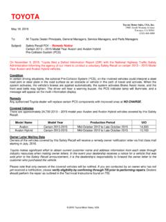
7 Unplug the 40-way electrical connector located on the bottom side of the TIPM (Figure 10). 14. Carefully remove and save the 40-way electrical connector wire cover located on the wire side of the connector (Figure 11). NOTE: The plastic tie strap that holds the wire harness to the wire cover must be cut off and discarded (Figure 10). Service Procedure (Continued) Figure 10 TIPM 40-Way Electrical Connector Figure 11 40-Way Electrical Connector Wire Cover NEW FUEL PUMP Relay WIRE HARNESS 40-WAY ELECTRICAL CONNECTOR CAVITY 40-WAY ELECTRICAL CONNECTOR NEW FUEL PUMP Relay TIPM ASSEMBLY 40-WAY ELECTRICAL CONNECTOR WIRE COVER 40-WAY ELECTRICAL CONNECTOR LOCK BAR Safety Recall P54 Fuel Pump Relay Page 9 15. Locate the blue (with an orange trace) wire in the 40-way electrical connector (Figure 12). 16. Cut the blue (with an orange trace) wire one inch (25 mm) from the 40-way electrical connector (Figure 13).
8 17. Install shrink tube to the connector side blue (with an orange trace) wire to insulate the wire end. This wire will no longer be used (Figure 13). Service Procedure (Continued) Figure 12 - Locate Blue with Orange Trace Wire in 40-Way Connector Figure 13 Cut the Blue (with Orange Trace) Wire BLUE (WITH ORANGE TRACE) WIRE THAT WILL BE SPLICED TO THE BLUE WIRE OF THE NEW FUEL PUMP Relay WIRE HARNESS 40-WAY ELECTRICAL CONNECTOR 40-WAY ELECTRICAL CONNECTOR LOCK BAR PLACE SHRINK TUBE OVER ABANDONED BLUE (WITH ORANGE TRACE) WIRE BLUE (WITH ORANGE TRACE) WIRE THAT WILL BE SPLICED TO THE BLUE WIRE ON THE NEW FUEL PUMP Relay WIRE HARNESS 40-WAY ELECTRICAL CONNECTOR SHRINK TUBE GLUE Safety Recall P54 Fuel Pump Relay Page 10 18. Using the following procedure, splice the blue (with an orange trace) wire on the wire harness to the blue wire on the new fuel pump Relay harness: a.
9 Strip approximately inch (13 mm) of insulation from the end of the blue wire on the new fuel pump Relay wire and the original blue (with an orange trace) wire (Figure 14). b. Place the black shrink tube provided in the repair kit over the cut wire (Figure 14). c. Using the supplied brass splice band clamps and crimp tool 10042, crimp the wire that had the insulation stripped on the wire harness side to the matching color wire on the fuel pump Relay wire harness (Figure 15). d. Solder the brass splice band clamp with rosin core solder (Figure 15). e. Slide the shrink tube evenly over the soldered brass splice band clamp and apply heat to the shrink tube until glue comes out of both ends of the shrink tube. Service Procedure (Continued) Figure 14 Strip Wire and Install Shrink Tube Figure 15 - Crimp and Solder Blue Wire to Blue Wire (with Orange Trace) NEW FUEL PUMP Relay WIRE HARNESS SHRINK TUBE STRIP IN.
10 (13 MM) OF WIRE INSULATION FROM THE END OF THE BLUE WIRE BLUE WIRE FROM NEW FUEL PUMP Relay WIRE HARNESS BRASS SPLICE BAND CLAMP CRIMP TOOL 10042 BLUE (WITH ORANGE TRACE) WIRE 40-WAY ELECTRICAL CONNECTOR Safety Recall P54 Fuel Pump Relay Page 11 19. Remove and save the 40-way electrical connector green plastic terminal lock (Figure 16). 20. Locate the pink (with green trace) wire in cavity 38 of the 40-way electrical connector (Figure 17). Service Procedure (Continued) Figure 16 Green Connector Lock Figure 17 Pink (with Green Tracer) Wire Location GREEN PLASTIC TERMINAL LOCK 40-WAY ELECTRICAL CONNECTOR 40-WAY ELECTRICAL CONNECTOR LOCK BAR 40-WAY ELECTRICAL CONNECTOR PINK (WITH GREEN TRACE) WIRE 40-WAY ELECTRICAL CONNECTOR LOCK BAR Safety Recall P54 Fuel Pump Relay Page 12 21. Carefully remove the pink (with a green trace) from the 40-way connector (Figure 18).