Transcription of Safety Relay - AutomationDirect
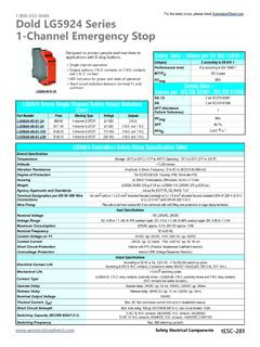
1 Safety Relays Selection ChartPart NumberPriceMarking TypeVoltage OutputsLG5925-48-61-24$ E-STOP / GATE24 VAC/DC3 and 1 $ E-STOP / GATE110 VAC3 and 1 $ E-STOP / GATE230 VAC3 and 1 Controllers Safety Relay Specification TableGeneral SpecificationsTemperatureStorage: -25 C to 85 C (-13 F to 185 F) Operating: -15 C to 55 C (5 F to 131 F)Altitude<2,000 metersVibration ResistanceAmplitude: , Frequency: 10 to 55 Hz (IEC/EN 60-068-2-6)Degree of ProtectionPer IEC/EN 60 529. Housing: IP40; Terminals IP20 HousingUL 94V-0 Thermoplastic; Din mount 35 mm x mm WeightLG5925 24V AC/DC: 210 g ( oz.); LG5925 110V, 230V AC: 275 g ( oz.)Agency Approvals and StandardsCSA, cULus file E107778, CE, RoHS, TUVT erminal Designation per EN 50 005 Wire Connections1x4 mm2 solid or 1 x mm2 stranded ferruled (isolated) or 2 x mm2 stranded ferruled (isolated) DIN 46 228-1/-2/-3/-4 or 2 x mm2 solid DIN 46 228-1/-2/-3/-4 Wire FixingTerminal screws box terminals with wire protection or cage clamp SpecificationsNominal Voltage110 VAC, 230 VAC, 24 VAC/DCVoltage RangeAt 10% residual ripple: AC/DC: to UN; AC: to UNMaximum ConsumptionDC approx.
2 ; AC approx. VA Nominal Frequency50 to 60 HzMinimum Off-time250 msControl Voltage on S11 At UNAC/DC units: 22 VDC; AC units: 24 VDCC ontrol Current Typ. Over S12, S2230mA at UNMin. Voltage on S12, S22 ( Relay activated)AC/DC units: 20 VDC; AC units: 19 VDC Short Circuit ProtectionInternal with PTC (Positive Temperature Coefficient resistor)Overvoltage ProtectionInternal VDR (Voltage Dependent Resistor)Output SpecificationsElectrical Contact LifeAC 15 at 5A, 230 VAC: > switching cycles Mechanical Life> 20x106 switching cyclesContact Type3 positively driven and 1 Relay contacts ( contacts are Safety contacts)Operate DelayManual start: 30ms; automatic start: 350ms Release DelayDisconnecting the supply: AC units:150ms; DC units: 50msDisconnecting S12, S22: AC units: 130ms. DC units: 50msNominal Output VoltageAC: 250V; DC: See continuous current limit curve in installation Current (Ith)Max.
3 8A. See continuous current limit curve in installation Circuit StrengthMax. fuse rating: 10A gL (IEC/EN 60 947-5-1); Line circuit breaker: B 6 ASwitching Capacity (IEC/EN 60 947-5-1)AC 15: contacts: 3A/230V; contacts: 2A/230 VDC 13: contacts: 4A/DC24V. ; contacts: 4A/24V; DC 13: contacts: 8A/24V >25x103. ON: , OFF: sSwitching FrequencyMax. 1200 switching cycles/hrDold LG5925 Series 2-Channel Emergency Stop and Safety GatesDesigned to protect people and machines in applications with E-stop buttons and Safety gates. Outputs: 3 contacts and 1 contact Feedback circuit to monitor external contactors used for reinforcement of contacts Overvoltage and short-circuit protection Monitored manual restart Single and 2-channel operation LED indicators for power and state of operationLG5925-48-61-24 Safety Data Values per EN ISO 13849-1 Category4 according to EN 954-1 Performance level PLe according to EN 13849-1 MTTFd>100 yearsDCavg99% Safety Data Values per IEC/EN 62061 /IEC/EN 61508 SIL CL3 per IEC/EN 62061 SIL3 per IEC/EN 61508 HFT (Hardware Failure Tolerance)1 DCavg99% Electrical ComponentstESC-287 For the latest prices, please check LG5925 Series 2-Channel Emergency Stop and Safety GatesWiringA1(+)A2(-)
4 S11S12S22 S33S3433 412313S2134 422414K2K2K1Po wer24VK1K1K2 Overvoltageandshortcircuit protectionMonitoringlogic2-channel emergency stop circuit with S1 cross fault detection S2 manual startContact reinforcement by external contactors, 2-channel output contacts can be reinforced by external contactors with positive guided contacts for switching currents > 8 of the external contactors is monitored by looping the contacts into the closing circuit (terminals S33-S34).Note: Refer to "Unit programming" S1 no cross fault detection S2 manual startL1NE-stopA2(-)A1(+) (-)A1(+) emergency stop circuit without Note: Refer to "Unit programming"S1 no cross fault detectionS2 manual startL1NE-stopA2(-)A1(+) channel emergency stop circuit. This circuit does not have any redundancy in the emergency-stop control : Refer to "Unit programming"Set switch or dip switch in pos.: S1 no cross fault detection S2 automatic startoffL1NE-stopA2(-)A1(+) reinforcement by external contactors controlled by one contact (-)A1(+) switch or dip switch in pos.
5 :Set switch or dip switch in pos.:2-channel Safety gate : Refer to "Unit programming" S1 no cross fault detection S2 manual startL1NA2(-)A1(+) contact(contactposition:closed)Set switch or dip switch in pos.:cross fault (-)A1(+)S11S33S34S12S22S21 OnK4K5BG5920S2 ++++------1323LG5925(+)(-)coded switchcoded actuatorcoded actuatorcoded switch2-channel emergency stop circuit with cross reinforcement by external coded non-contact sensors in : Refer to Unit programming Set switch or dip switch in pos.: S2 Manual or Automatic (dotted jumper)S1 cross fault detectioncross fault : Refer to "Unit programming"Note: Refer to "Unit programming"S1 no cross fault detectionS2 automatic startSet switch or dip switch in pos.:Set switch or dip switch in pos.:LG5925 Block DiagramApplicationsNote: When switching inductive loads, surge suppressors are mm [in] Electrical ComponentstESC-288 For the latest prices, please check Relays Selection ChartPart NumberPriceMarking TypeVoltage OutputsLG5929-60-100-61$ Relay extension module24 VAC/VDC5 Relay Extenson Module Specification TableGeneral SpecificationsTemperatureStorage: -25 C to 85 C (-13 F to 185 F) Operating: -15 C to 55 C (5 F to 131 F)Altitude< 2,000 metersVibration ResistanceAmplitude: , Frequency: 10 to 55 Hz (IEC/EN 60-068-2-6)Degree of ProtectionPer IEC/EN 60 529.
6 Housing: IP40; Terminals IP20 HousingUL 94V-0 Thermoplastic; Din mount 35 mm x mm Weight205g ( oz.) Agency Approvals and StandardsCSA, cULus file E107778, CE, RoHS, TUVT erminal Designation per EN 50 005 Wire Connections1x4 mm2 solid or 1 x mm2 stranded ferruled (isolated) or 2 x mm2 stranded ferruled (isolated) DIN 46 228-1/-2/-3/-4 or 2 x mm2 solid per DIN 46 228-1/-2/-3 /-4 Wire FixingPlus-minus terminal screws box terminals with wire protection or cage clamp terminals. Input SpecificationsNominal Voltage24V AC/DCVoltage RangeAC: to UNAt 10% residual ripple: to UN; At 48% residual ripple: to UNMaximum Consumption24 VAC/DC: Frequency50 to 60 HzControl CurrentControl current typ. at 24V over 2 relays: 75 mAOvervoltage ProtectionInternal VDR (Voltage Dependent Resistor)Output SpecificationsElectrical Contact LifeTo AC15 at 2 A,230V: 105 switching cycles IEC/EN 60 947-5-1 Mechanical Life20 x 106 switching cyclesContact Type5 positively driven and 1 Relay contacts ( contacts are Safety contacts)Operate/Release TimeOperate typ at UN: 20 m.
7 ; Release typ at UN: 35 Output Voltage250 VAC Thermal Current (Ith)Max. 5A per contact. See continuous current limit curve in installation Circuit StrengthMax fuse rating:10A gl (IEC/EN 60 9470-5-1); Line circuit breaker: B6 ASwitching Capacity IEC/EN 60 947-5-1 AC 15: contacts: 3A/230V; contacts: 2A/230 VAC DC 13: contacts: 4A/24V; contacts: 4A/24 VDC; contact: 8A/24V >25x103 ON: , OFF: FrequencyMax. 1,200 switching cycles/hrDold LG5929 Extension ModuleAdditional contacts for emergency-stop modules and Safety gate monitors. 1-channel or 2-channel connection LED indication for operation Output: 5 and 1 contactsSafety Data Values per EN ISO 13849-1 Category4 according to EN 954-1 Performance levelPLe according to EN 13849-1 MTTFd>100 yearsDCavg99% Safety Data Values per IEC/EN 62061 /IEC/EN 61508 SIL CL3 per IEC/EN 62061 SIL3 per IEC/EN 61508 HFT (Hardware Failure Tolerance)1 DCavg99% Electrical ComponentstESC-333 For the latest prices, please check Block Diagram1323334353Y11424344454Y2A1(+)A2(- )A3(+)A4(-)K1K224V24V Dold LG5929 Extension ModuleWiringDimensions mm [in]Contact multiplication with LG 5929/100A1(+)A2(-)A2(-)A4(-)A1(+)A3(+)S1 2S22131323233343LG5925LG5929 *Note: When switching inductive loads, surge suppressors are recommended.
8 Note: This is a representative drawing. Depending on the LG5925 Safety Relay you select, different voltage sources may be Electrical ComponentstESC-334 For the latest prices, please check ProductsWarning: Safety products sold by AutomationDirect are Safety components only. The purchaser/installer is solely responsible for the application of these components and ensuring all necessary steps have been taken to assure each application and use meets all performance and applicable Safety requirements and/or local, national and/or international Safety codes as required by the application. AutomationDirect cannot certify that our products, used solely or in conjunction with other AutomationDirect or other vendors products, will assure Safety for any application. Any person using or applying any products sold by AutomationDirect is responsible for learning the Safety requirements for their individual application and applying them, and therefore assumes all risks, and accepts full and complete responsibility, for the selection and suitability of the product for their respective application.
9 AutomationDirect does not provide design or consulting services, and cannot advise whether any specific application or use of our products would ensure compliance with the Safety requirements for any application. Electrical ComponentstESC-148 For the latest prices, please check