Transcription of Sauer Danfoss Series 90 Hydraulic Axial Piston Pump
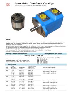
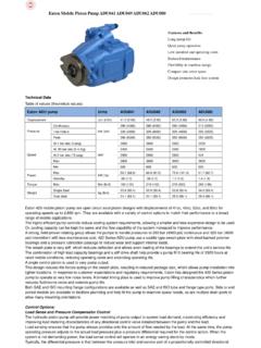
1 Sauer Danfoss Series 90 Hydraulic Axial Piston Pump 90R030, 90R042, 90R055, 90R075, 90R100, 90R130, 90R180, 90R250 90L030, 90L042, 90L055, 90L075, 90L100, 90L130, 90L180, 90L250 Series 90 advanced technology Seven sizes of variable displacement pumps Proven reliability and performance Compact, lightweight Worldwide sales and service PLUS+1 compliant controls and sensors Series 90 variable displacement pump is compact, high power density units. All models utilize the parallel Axial Piston /slipper concept in conjunction with a tilt able swash plate to vary the pump s displacement. Reversing the angle of the swash plate reverses the flow of oil from the pump and thus reverses the direction of rotation of the motor output. Series 90 pumps include an integral charge pump to provide system replenishing and cooling oil flow, as well as control fluid flow.
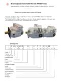
2 They also feature a range of auxiliary mounting pads to accept auxiliary Hydraulic pump for use in complementary Hydraulic systems. A complete family of control options is available to suit a variety of control systems (mechanical, Hydraulic , electric). Series 90 motor also use the parallel Axial Piston /slipper design in conjunction with a fixed or tilt able swash plate. They can intake/discharge fluid through either port; they are bidirectional. They also include an optional loop flushing feature that provides additional cooling and cleaning of fluid in the working loop. Series 90 Hydraulic pump and motor can be applied together or combined with other products in a system to transfer and control Hydraulic power. They are intended for closed circuit applications. Series 90 pumps can be used together in combination with other Sauer - Danfoss pump and motor in the overall Hydraulic system.
3 Sauer - Danfoss Hydraulic products are designed with many different displacement, pressure and load-life capabilities. General Specifications Design Axial Piston pump of cradle swash plate design with variable displacement Direction of rotation Clockwise, counterclockwise Pipe connections Main pressure ports: ISO split flange boss Remaining ports: SAE straight thread O-ring boss Recommended installation position Pump installation position is discretionary; however the recommended control position is on the top or at the side, with the top position preferred. Vertical input shaft installation is acceptable. If input shaft is at the top 1 bar case pressure must be maintained during operation. The pump housing must be filled with Hydraulic fluid under all conditions; including after a long period of shutdown. Before operating the machine, ensure the pump housing and case drain lines are free of air.
4 Recommended mounting for a multiple pump stack is to arrange the highest power flow towards the input source. Auxiliary cavity pressure Will be inlet pressure with internal charge pump. For reference see operating parameter on next page. Will be case pressure with external charge supply. Please verify mating pump shaft seal capability. Technical Information: Overview This section defines the operating parameters and limitations for Series 90 pumps with regard to input speeds and pressures. For actual parameters, refer to the Operating parameters for each displacement. Input Speed: Minimum speed is the lowest input speed recommended during engine idle condition. Operating below minimum speed limits the pump s ability to maintain adequate flow for lubrication and power transmission. Rated speed is the highest input speed recommended at full power condition. Operating at or below this speed should yield satisfactory product life.
5 Maximum speed is the highest operating speed permitted. Exceeding maximum speed reduces product life and can cause loss of hydrostatic power and braking capacity. Never exceed the maximum speed limit under any operating conditions. Operating conditions between Rated speed and Maximum speed should be restricted to less than full power and to limited periods of time. For most drive systems, maximum unit speed occurs during downhill braking or negative power conditions. During Hydraulic braking and downhill conditions, the prime mover must be capable of providing sufficient braking torque in order to avoid pump over speed. This is especially important to consider for turbocharged and Tier 4 engines. System Pressure System pressure is the differential pressure between high pressure system ports. It is the dominant operating variable affecting Hydraulic unit life. High system pressure, which results from high load, reduces expected life.
6 Hydraulic unit life depends on the speed and normal operating, or weighted average, pressure that can only be determined from a duty cycle analysis. Application pressure is the high pressure relief or pressure limiter setting normally defined within the order code of the pump. This is the applied system pressure at which the drive-line generates the maximum calculated pull or torque in the application. Maximum working pressure is the highest recommended Application pressure. Maximum working pressure is not intended to be a continuous pressure. Propel systems with application pressures at, or below, this pressure should yield satisfactory unit life given proper component sizing. Maximum pressure is the highest allowable Application pressure under any circumstance. Application pressures above maximum working Pressure will only be considered with duty cycle analysis and factory approval.
7 Pressure spikes are normal and must be considered when reviewing maximum working pressure. Minimum low loop pressure must be maintained under all operating conditions to avoid cavitations. All pressure limits are differential pressures referenced to low loop (charge) pressure. Subtract low loop pressure from gauge readings to compute the differential. Servo Pressure Servo pressure is the pressure in the Servo-system needed to position and hold the pump on stroke. It depends on system pressure and speed. At minimum servo pressure the pump will run at reduced stroke depending on speed and pressure. Minimum servo pressure at corner power holds the pump on full stroke at max speed and max pressure. Maximum servo pressure is the highest pressure typically given by the charge pressure setting. Charge Pressure An internal charge relief valve regulates charge pressure.
8 Charge pressure supplies the control with pressure to operate the swash plate and to maintain a minimum pressure in the low side of the transmission loop. The charge pressure setting listed in the order code is the set pressure of the charge relief valve with the pump in neutral, operating at 1800 min-1 [rpm], and with a fluid viscosity of 32 mm2/s [150 SUS]. Pumps configured with no charge pump (external charge supply) are set with a charge flow of 30 l/min. [ US gal/min.] and a fluid viscosity of 32 mm2/s [150 SUS]. The charge pressure setting is referenced to case pressure. Charge pressure is the differential pressure above case pressure. Minimum charge pressure is the lowest pressure allowed to maintain a safe working condition in the low side of the loop. Minimum control pressure requirements are a function of speed, pressure, and swash plate angle, and may be higher than the minimum charge pressure shown in the Operating parameters tables.
9 Maximum charge pressure is the highest charge pressure allowed by the charge relief adjustment, and which provides normal component life. Elevated charge pressure can be used as a secondary means to reduce the swash plate response time. At normal operating temperature charge inlet pressure must not fall below rated charge inlet pressure (vacuum). Minimum charge inlet pressure is only allowed at cold start conditions. In some applications it is recommended to warm up the fluid ( in the tank) before starting the engine and then run the engine at limited speed. Maximum charge pump inlet pressure may be applied continuously. Case Pressure Under normal operating conditions, the rated case pressure must not be exceeded. During cold start case pressure must be kept below maximum intermittent case pressure. Size drains plumbing accordingly. Auxiliary Pad Mounted Pumps.
10 The auxiliary pad cavity of S90 pumps configured without integral charge pumps is referenced to case pressure. Units with integral charge pumps have auxiliary mounting pad cavities referenced to charge inlet (vacuum). External Shaft Seal Pressure In certain applications the input shaft seal may be exposed to external pressure. In order to prevent damage to the shaft seal the maximum differential pressure from external sources must not exceed bar ( psi) over pump case pressure. The case pressure limits of the pump must also be followed to ensure the shaft seal is not damaged. Temperature and Viscosity Temperature: The high temperature limits apply at the hottest point in the transmission, which is normally the motor case drain. The system should generally be run at or below the quoted rated temperature. The maximum intermittent temperature is based on material properties and should never be exceeded.