Transcription of Screw Thread Design - Industrial Supplies, OEM Fasteners ...
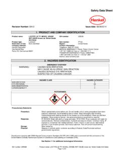
1 Rev. 3-4-09 Screw Thread Design Screw Thread fundamentals A Screw Thread is defined as a ridge of uniform section in the form of a helix on either the external or internal surface of a cylinder. Internal threads refer to those on nuts and tapped holes, while external threads are those on bolts, studs, or screws. The Thread form is the configuration of the Thread in an axial plane; or more simply, it is the profile of the Thread , composed of the crest, root, and flanks. At the top of the threads are the crests, at the bottom the roots, and joining them are the flanks.
2 The triangle formed when the Thread profile is extended to a point at both crests and roots, is the fundamental triangle. The height of the fundamental triangle is the distance, radially measured, between sharp crest and sharp root diameters. The distance measured parallel to the Thread axis, between corresponding points on adjacent threads, is the Thread pitch. Unified Screw threads are designated in threads per inch. This is the number of complete threads occurring in one inch of threaded length. Metric Thread pitch is designated as the distance between threads (pitch) in millimeters.
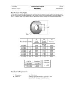
3 On an internal Thread , the minor diameter occurs at the crests and the major diameter occurs at the roots. On an external Thread , the major diameter is at the Thread crests, and the minor diameter is at the Thread roots. The flank angle is the angle between a flank and the perpendicular Thread axis. Flank angles are sometimes termed half-angle of the Thread , but this is only true when neighboring flanks have identical angles; that is, the threads are symmetrical. Unified Screw threads have a 30 flank angle and are symmetrical. This is why they are commonly referred to as 60 degree threads.
4 Pitch diameter is the diameter of a theoretical cylinder that passes through the threads in such a way that the distance between the Thread crests and Thread roots is equal. In an ideal product, these widths would each equal one-half of the Thread pitch. Threads Per Inch Thread Pitch Rev. 3-4-09 An intentional clearance is created between mating threads when the nut and bolt are manufactured. This clearance is known as the allowance. Having an allowance ensures that when the threads are manufactured there will be a positive space between them.
5 For Fasteners , the allowance is generally applied to the external Thread . Tolerances are specified amounts by which dimensions are permitted to vary for convenience of manufacturing. The tolerance is the difference between the maximum and minimum permitted limits. Thread Fit Thread fit is a combination of allowances and tolerances and a measure of tightness or looseness between them. A clearance fit is one that provides a free running assembly and an interference fit is one that has a positive interference thus requiring tools for the initial run-down of the nut.
6 For Unified inch Screw threads there are six standard classes of fit: 1B, 2B, and 3B for internal threads; and 1A, 2A, and 3A for external threads. All are considered clearance fits. That is, they assemble without interference. The higher the class number, the tighter the fit. The A designates an external Thread , and B designates an internal Thread . Classes 1A and 1B are considered an extremely loose tolerance Thread fit. This class is suited for quick and easy assembly and disassembly. Outside of low-carbon threaded rod or machine screws, this Thread fit is rarely specified.
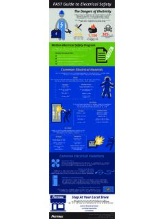
7 Classes 2A and 2B offer optimum Thread fit that balances fastener performance, manufacturing, economy, and convenience. Nearly 90% of all commercial and Industrial Fasteners use this class of Thread fit. Classes 3A and 3B are suited for close tolerance Fasteners . These Fasteners are intended for service where safety is a critical Design consideration. This class of fit has restrictive tolerances and no allowance. Socket products generally have a 3A Thread fit. The following illustration demonstrates the pitch diameter allowances on a -10 bolt and nut.
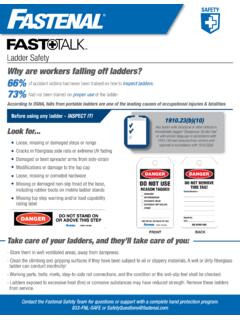
8 The axial distance through which the fully formed threads of both the nut and bolt are in contact is called the length of Thread engagement. The depth of Thread engagement is the distance the threads overlap in a radial direction. The length of Thread engagement is one of the key strength aspects and one of the few which the designer may be able to control. Rev. 3-4-09 Per the acceptance requirements of ASME , System 21, the allowance specified for the Class 2A external threads is used to accommodate the plating thickness. The plain finished parts (or plated parts prior to plating) would be tested for adherence to these tolerances with a 2A Go/No-Go Thread gauge.
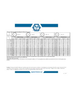
9 The 2A Go gauge would ensure the pitch diameter falls below the maximum requirement; the No-Go gauge would verify that the pitch diameter is above the minimum requirement. A standard electro-zinc plated 2A part would be gauged with the Class 3A Go (due to the plating metal thickness) and 2A No-Go gauge after plating. Thread damages such as dents, scrapes, nicks, or gouges and plating build-up are not cause for rejections unless they impair function and usability. Threads that do not freely accept the appropriate Go ring gauge shall be inspected by allowing the screwing of the gauge with maximum allowable torque value of: Torque = 145 x d3 (for inch series), where Torque is in-lbs.
10 And d is diameter in inches- IFI 166 Torque = x d3 (for metric series), where Torque is Nm and d is diameter in mm- IFI 566 Thread Series There are three standard Thread series in the Unified Screw Thread system that are highly important for Fasteners : UNC (coarse), UNF (fine), and 8-UN (8 Thread ). A chart listing the standards sizes and Thread pitches with their respective Thread stress areas is listed in the Fastenal Technical Reference Guide, along with a special series designated UNS. Below are some of the aspects of fine and coarse threads.