Transcription of SCU-17 USB INTERFACE UNIT - Yaesu
1 SCU-17 USB INTERFACE unit . Instruction Manual 18 . Introduction Introduction The SCU-17 INTERFACE unit may be used for CAT control of the transceiver with a computer via a USB connection; and for communications using SSTV, RTTY. and PSK digital modes. Note: Yaesu does not produce CAT, SSTV, RTTY and PSK System operating software, due to the wide variety of personal computers, operating sys- tems, and applications in use today. The SCU-17 provides CAT communication through the USB terminal when a PC does not have an RS-232C connection. The SCU-17 is equipped with a USB audio system device, so the TX and RX. audio system signals are accessible to the SCU-17 through the USB cable. Therefore, the supplied USB cable is the only connection needed between the SCU-17 and PC. The SCU-17 is equipped with a two-channel USB serial device and enables the various transmission modes and the CAT communication simultaneously.
2 The SCU-17 operates from the USB bus power; you do not need to prepare an external power supply. For RF isolation, the SCU-17 is designed with photo relays for the PTT/FSK. terminals. AF transformers are used in the AUDIO IN/OUT lines to provide excellent ground isolation. The SCU-17 is equipped with the TX and RX audio controls on the front pan- el, for convenient level adjustment. LED indicators on the SCU-17 front panel monitor the PTT and FSK control. The operating conditions may be quickly confirmed. When using the SCU-17 to perform TX control, the transceiver may switch to transmit mode when the computer is started. SCU-17 USB INTERFACE unit 1. Virtual COM port driver Installation Install the virtual COM port driver on the personal computer before using the SCU-17 USB INTERFACE unit . Please see the USB Driver (Virtual COM Port Driver) on the Yaesu Website for details refer to ( ) in the FTDX1200 product files section.
3 Note: Do not connect the USB cable and SCU-17 to your personal computer until after the virtual COM port driver installation is completed, because an incorrect driver may be installed. For assistance with the software port configuration, refer to How to Confirm the Installation, and the COM Port Number in the Virtual COM port Driver Installation Manual . For information on port configuration for commercial and free computer soft- ware, refer to the manual for the software being used. When using the USB cable to supply TX and RX audio signals, set the Sound Card (input and output) settings to USB Audio CODEC . When using the USB cable for computer TX control, the transceiver may switch to transmit mode when the computer is started, etc. Yaesu does not provide technical support for the use or operation of com- mercial or free computer software. 2 SCU-17 USB INTERFACE unit Accessories USB cable (Type A male to Type B male).
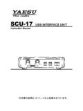
4 1 pc RS-232C cable (female to female, Straight Type).. 1 pc N/A N/A. SERIAL IN RTS. SERIAL OUT CTS. N/A NC. GND. Connection cable (MDIN6P - MDIN6P).. 1 pc . DATA OUT FSK OUT. GND DATA IN. DATA PTT SQL IN.. mm Stereo plug .. 2 pcs GND PTT GND IN. FSK OUT. PTT/FSK AUDIO. Instruction manual SCU-17 USB INTERFACE unit 3. Controls & Connections Fr ont Panel . Rear Panel . RX audio level control knob This knob adjusts the RX audio level. TX audio level control knob This knob adjusts the TX audio level. FSK Indicator This indicator illuminates when the Mark frequency is shifted. TX Indicator This indicator illuminates during transmission. POWER Indicator USB Connector Connect to a computer from this jack using the supplied USB cable. CAT/RS-232C Jack This 9-pin serial DB-9 jack allows CAT communication of the transceiver. Connect a supplied RS-232C cable here and to the transceiver. mm stereo Jack (PTT/FSK). This 3-conductor, mm stereo jack is used for PTT/FSK.
5 For RF isolation, these terminals are designed with photo relays. DATA Jack This 6-pin (MDIN6P) jack allows DATA communication of the transceiver. mm stereo Jack (Audio IN/OUT). This 3-conductor, mm stereo jack is used for Audio IN/OUT. For RF isolation, AF transform- ers are used in the AUDIO IN/OUT lines. This Jack is equipped with an attenuator that is applied to the audio output. See page 15 for details about attenuation. 4 SCU-17 USB INTERFACE unit System Setup FTDX1200. FTDX1200. RTTY/DATA CAT. USB port Supplied Connection Cable Supplied USB Cable Supplied RS-232C Cable FT-950. FT-950. RTTY/PKT CAT. USB port Supplied Connection Cable Supplied USB Cable Supplied RS-232C Cable SCU-17 USB INTERFACE unit 5. System Setup FT-2000 Series / SCU-21. FT-2000 Series PACKET RTTY CAT. USB port Supplied RS-232C Cable Connection Cable "SCU-21" (option) Supplied USB Cable 6 SCU-17 USB INTERFACE unit System Setup FT-2000 Series / CT-39/A.
6 FT-2000 Series CAT. USB port Packet INTERFACE Cable "CT-39/A" (option) Supplied USB Cable Supplied RS-232C Cable SCU-17 DATA Jack Pin # CT-39 CT-39A. #1 Black Brown #2 Brown Red #3 Red Orange #4 Orange* Yellow #5 Yellow Green #6 Green Blue Shell Shield (BLK). * : The CT-39 orange wire may be white DATA IN SQL IN DATA IN DATA PTT. (Pin #5) (Pin #6) (Pin #5) (Pin #3). DATA OUT (Pin #1) DATA PTT (Pin #3). FSK OUT GND. GND (Pin #4) (Pin #2). (Pin #2). (as viewed from rear panel). SCU-17 USB INTERFACE unit 7. System Setup FTDX9000 Series / SCU-22. FTDX9000 Series CAT PACKET RTTY. USB port Supplied RS-232C Cable Supplied USB Cable Connection Cable "SCU-22" (option). 8 SCU-17 USB INTERFACE unit System Setup FTDX9000 Series / CT-39/A. FTDX9000 Series CAT. USB port Supplied RS-232C Cable Supplied USB Cable Packet INTERFACE Cable "CT-39/A" (option). SCU-17 DATA Jack Pin # CT-39 CT-39A. #1 Black Brown #2 Brown Red #3 Red Orange #4 Orange* Yellow #5 Yellow Green #6 Green Blue Shell Shield (BLK).
7 * : The CT-39 orange wire may be white DATA IN SQL IN DATA PTT GND. (Pin #5) (Pin #6) (Pin # 3) (Pin #2). DATA OUT (Pin#1) DATA IN FSK OUT. (Pin #5) (Pin #4). GND. (Pin #2). (as viewed from rear panel). SCU-17 USB INTERFACE unit 9. System Setup FTDX5000 Series / SCU-21. FTDX5000 Series PACKET RTTY CAT. USB port Supplied RS-232C Cable Connection Cable "SCU-21" (option) Supplied USB Cable 10 SCU-17 USB INTERFACE unit System Setup FTDX5000 Series / CT-39/A. FTDX5000 Series CAT. USB port Packet INTERFACE Cable "CT-39/A" (option) Supplied USB Cable Supplied RS-232C Cable SCU-17 DATA Jack Pin # CT-39 CT-39A. #1 Black Brown #2 Brown Red #3 Red Orange #4 Orange* Yellow #5 Yellow Green #6 Green Blue Shell Shield (BLK). * : The CT-39 orange wire may be white DATA IN SQL IN DATA IN DATA PTT. (Pin #5) (Pin #6) (Pin #5) (Pin #3). DATA OUT (Pin #1) DATA PTT (Pin #3). FSK OUT GND. GND (Pin #4) (Pin #2). (Pin #2). (as viewed from rear panel).
8 SCU-17 USB INTERFACE unit 11. System Setup FT-450D. FT-450D. DATA CAT. USB port Supplied Connection Cable Supplied USB Cable Supplied RS-232C Cable FT-817ND. FT-817ND. USB port DATA ACC. Supplied Connection Cable Supplied USB Cable CAT INTERFACE Cable "CT-62" (option). 12 SCU-17 USB INTERFACE unit System Setup FT-857D. FT-857D. CAT/LINEAR DATA USB port Supplied Connection Cable Supplied USB Cable CAT INTERFACE Cable "CT-62" (option). SCU-17 USB INTERFACE unit 13. System Setup FT-897D. FT-897D. CAT/LINEAR DATA USB port Supplied Connection Cable Supplied USB Cable CAT INTERFACE Cable "CT-62" (option). Interfacing to other transceivers USB port Supplied USB Cable mm Stereo plug 14 SCU-17 USB INTERFACE unit PTT/FSK control and Attenuator Setting The PTT/FSK setting may be changed and the audio output attenuator may be enabled by changing the configuration of an internal switch and a jumper. 1. Disconnect all the cables from the SCU-17 .
9 2. Referring to Figure 1, remove the 4 screws attaching the top case, then re- move the top case. 3. Refer to Figure 2 for the location of switch (S1001) and jumper (J1006). 4. Set the switch (S1001) and jumper (J1006). S1001: PTT/FSK control setting J1006: Attenuator setting to the audio output of the Audio IN/OUT jack. 5. Replace the top case, using the 4 screws removed in step (2) above. 6. Reconnect the cables to the SCU-17 . Figure 1. S1001. PTT : RTS. FSK : DTR. PTT : DTR. FSK : RTS J1006. ATT : OFF. (100 mVrms). ATT : ON. ( mVrms). Figure 2. SCU-17 USB INTERFACE unit 15. Specifications Supply Voltage: DC V 5%, Negative Ground Current Consumption: 130 mA. Data Jack: PTT: Maximum output +25 V, 50 mA (open collector). FSK: Maximum output +25 V, 50 mA (open collector). DATA-IN: 100 mVrms @ 10 k Ohms DATA-OUT: 100 mVrms @ 600 Ohms FSK/PTT Jack: PTT: Maximum output +30 V, 250 mA (open drain). FSK: Maximum output +30 V, 250 mA (open drain).
10 AUDIO Jack: AUDIO-IN: 100 mVrms @ 600 Ohms AUDIO-OUT: 100 mVrms @ 600 Ohms CAT/RS-232C Jack: RS-232C voltage level USB Connector: USB or USB , USB bus power Case Size: (W) x (H) x (D) (111 x x mm). Weight (approx.): oz (230 g). 16 SCU-17 USB INTERFACE unit Note This device complies with part 15 of the FCC Rules. Operation is subject to the following two condi- tions; (1) this device may not cause harmful interference, and (2) this device must accept any interfer- ence including interference that may cause undesired operation. This equipment has been tested and found to comply with the limits for a Class B digital device, pursuant to Part 15 of the FCC Rules. These limits are designed to provide reasonable protection against harmful interference in a residential installation. This equipment generates, uses and can radiate radio frequency energy and, if not installed and used in accordance with the instructions, may cause harmful interference to radio communications.