Transcription of SD-01-333 Bendix Tu-Flo 550 Air Compressor
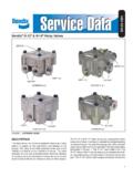
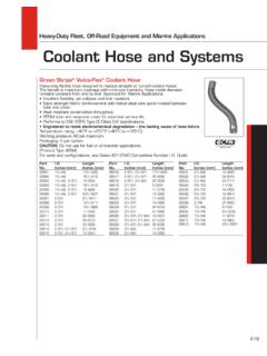
1 1 SD-01-333 Bendix Tu-Flo 550 Air CompressorBENDIX Tu-Flo 550 AIR Compressor (CROSS SECTION) Bendix Tu-Flo 550 AIR Compressor (EXTERIOR)AIR DISCHARGEWATER OUTLETPIECE RINGSPISTONCRANKSHAFTCONNECTINGRODINLET VALVE SEATUNLOADERINLET VALVECYLINDERHEADEND VIEW OF CYLINDER HEADDISCHARGEVALVE SPRINGDISCHARGEVALVEDISCHARGEVALVE STOPAIR INLETCRANKCASEINLETINLET VALVESPRINGDESCRIPTIONThe function of the air Compressor is to provide and maintain air under pressure to operate devices in the air brake and/or auxiliary air systems.
2 The Bendix Tu-Flo 550 Compressor is a two cylinder single stage, reciprocating Compressor with a rated displacement of cubic feet per minute at 1250 Compressor assembly consists of two major subassemblies, the cylinder head and the crankcase. The cylinder head is an iron casting which houses the inlet, discharge, and unloader valving. (See Figure 1.) The cylinder head contains the air inlet port and is designed with both top and side air discharge ports. Three water coolant ports provide a choice of coolant line connections.
3 Governor mounting surfaces are provided at both the front and the rear of the cylinder head. The head is mounted on the crankcase and is secured by six cap screws. The Tu-Flo 550 Compressor is designed such that the cylinder head can be installed in one of two positions which are 180 degrees apart. The crankcase houses the cylinder bores, pistons, crankshaft and main bearings, and provides the fl ange or base mounting SEATUNLOADERCOVERWATERINLET2 OPERATIONThe Compressor is driven by the vehicle engine and is operating continuously while the engine is running.
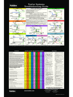
4 Actual compression of air is controlled by the Compressor unloading mechanism and the governor. The governor which is generally mounted on the Compressor maintains the brake system air pressure to a preset maximum and minimum pressure AND COMPRESSION OF AIR (LOADED)During the down stroke of the piston, a slight vacuum is created between the top of the piston and the cylinder head, causing the inlet valve to move off its seat and open. (Note: The discharge valve remains on its seat.) Atmospheric air is drawn through the air strainer and the open inlet valve into the cylinder (see Figure 4).
5 As the piston begins its upward stroke, the air that was drawn into the cylinder on the down stroke is being compressed. Air pressure on the inlet valve plus the force of the inlet spring, returns the inlet valve to its seat and closes. The piston continues the upward stroke and compressed air pushes the discharge valve off its seat and air fl ows by the open discharge valve, into the discharge line and to the reservoirs (see Figure 5). As the piston reaches the top of its stroke and starts down, the discharge valve spring and air pressure in the discharge line returns the discharge valve to its seat.
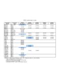
6 This prevents the compressed air in the discharge line from returning to the cylinder bore as the intake and compression cycle is MACK(MACK STYLE)DETROITDIESELAIR INLETWATERUNLOADER COVER PLATEAIR DISCHARGEWATERAIRDISCHARGEGOVERNORWATERM ANUFACTURED BY BENDIXTU-FLO 550 COMPRESSORBENDIX "FOXHEAD"CUMMINSMACKEXTENDEDFIGURE 2 - FLANGE CONFIGURATIONSV arious mounting and drive confi gurations, as shown in Figure 2, are supplied as required by the vehicle engine designs. A nameplate identifying the Compressor piece number and serial number is attached to the side of the crankcase.
7 (Reference Figure 3.)FIGURE 3 - NAMEPLATEFIGURE 1 - CYLINDER HEADCATBASEMOUNT3force the pistons upward and the inlet valves return to their seats. Compression is then & THE AIR BRAKE SYSTEMGENERALThe Compressor is part of the total air brake system, more specifi cally, the charging portion of the air brake system. As a component in the overall system its condition, duty cycle, proper installation and operation will directly affect other components in the by the vehicle engine, the air Compressor builds the air pressure for the air brake system.
8 The air Compressor is typically cooled by the engine coolant system, lubricated by the engine oil supply and has its inlet connected to the engine induction the atmospheric air is compressed, all the water vapor originally in the air is carried along into the air system, as well as a small amount of the lubricating oil as vapor. If an air dryer is not used to remove these contaminants prior to entering the air system, the majority, but not all, will condense in the reservoirs. The quantity of contaminants that reach the air system depends on several factors including installation, maintenance and contaminant handling devices in the system.
9 These contaminants must either be eliminated prior to entering the air system or after they CYCLEThe duty cycle is the ratio of time the Compressor spends building air to the total engine running time. Air compressors are designed to build air (run "loaded") up to 25% of the time. Higher duty cycles cause conditions that affect air GOVERNORPORTAIRINLETPORTINLETVALVEOPENPI STONMOVINGDOWNDISCHARGEVALVECLOSEDGOVERN ORPORTINLETVALVECLOSEDPISTONMOVINGUPFIGU RE 4 - OPERATIONAL-LOADED (INTAKE)FIGURE 5 - OPERATIONAL-LOADED (COMPRESSION)GOVERNORPORTDISCHARGEPORTAI RINLETPORTFIGURE 6 - OPERATIONAL-UNLOADEDDISCHARGEVALVECLOSED DISCHARGEVALVEOPENAIRINLETPORTNON-COMPRE SSION OF AIR (UNLOADED)
10 When air pressure in the reservoir reaches the cut-out setting of the governor, the governor allows air to pass from the reservoir, through the governor and into the cavity above the unloader pistons. The unloader pistons move down holding the inlet valves off their seats (see Figure 6.)With the inlet valves held off their seats by the unloader pistons, air is pumped back and forth between the two cylinders, and the discharge valves remain closed. When air pressure from the reservoir drops to the cut-in setting of the governor, the governor closes and exhausts the air from above the unloader pistons.