Transcription of SD-03-4516 Bendix SR-5 Trailer Spring Brake Valve
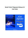
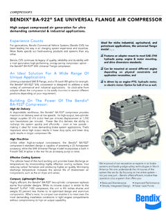
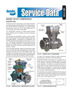
1 1SD-03-4516 Bendix SR-5 Trailer Spring Brake ValveFigure 1 - Bendix SR-5 Trailer Spring Brake Valve (*shown with optional anti-compounding cover)SR-5 Valve IDENTIFICATION HOLE1/4 NPT Trailer SERVICE1/4 NPT Trailer SUPPLY3/8 NPT DELIVERY (4)COVER*1/4 NPT SERVICE RESERVOIR (2)EXHAUST1/2 OR 3/4 NPT Spring Brake RESERVOIRPRESSURE PROTECTION VALVEDESCRIPTIONThe Bendix SR 5 Valve is a reservoir mounted Trailer Valve that can control up to four Spring Brake actuators during parking or emergency applications. It has the following capabilities: Automatically applies Trailer Spring brakes in the event of a breakaway or Trailer supply line failure. Protects Trailer reservoir(s) air pressure in the event of a breakaway or Trailer supply line failure. Allows no automatic Trailer Spring Brake application with air pressure loss in Trailer reservoir(s). Allows the Trailer Spring brakes to be applied and released repeatedly with a failed Trailer reservoir(s): Optional anti compounding prevents an overriding service Brake signal while the Trailer supply line is at atmospheric pressure.
2 Does not allow service system charging if a failure occurs in the parking Brake 1/2" or 3/4" NPT Spring Brake Reservoir Mounting (SPR BK RES)1 1/4" 18 NPT Trailer Supply (TRL SUP)1 1/4" 18 NPT Trailer Service (TRL SER)4 3/8" 18 NPT Delivery (DEL)2 1/4" 18 Service Reservoir (SERV RES)1 Exhaust (EXH)The SR 5 Valve appears very similar to the Bendix SR 2 Valve . Both valves consist of a die cast aluminum body and cover, pressure protection Valve , and reservoir mounting nipple. However, Figure 1 notes the distinguishing characteristic of the SR 5 Valve a hole drilled into the flat surface between the pressure protection Valve and the SAFETY GUIDELINESWARNING! PLEASE READ AND FOLLOW THESE INSTRUCTIONSTO AVOID PERSONAL INJURY OR DEATH:When working on or around a vehicle, the following guidelines should be observed AT ALL TIMES: Park the vehicle on a level surface, apply the parking brakes and always block the wheels.
3 Always wear personal protection equipment. Stop the engine and remove the ignition key when working under or around the vehicle. When working in the engine compartment, the engine should be shut off and the ignition key should be removed. Where circumstances require that the engine be in operation, EXTREME CAUTION should be used to prevent personal injury resulting from contact with moving, rotating, leaking, heated or electrically-charged components. Do not attempt to install, remove, disassemble or assemble a component until you have read, and thoroughly understand, the recommended procedures. Use only the proper tools and observe all precautions pertaining to use of those tools. If the work is being performed on the vehicle s air Brake system, or any auxiliary pressurized air systems, make certain to drain the air pressure from all reservoirs before beginning ANY work on the vehicle.
4 If the vehicle is equipped with a Bendix AD-IS air dryer system, a Bendix DRM dryer reservoir module, or a Bendix AD-9si air dryer, be sure to drain the purge reservoir. Following the vehicle manufacturer s recommended procedures, deactivate the electrical system in a manner that safely removes all electrical power from the vehicle. Never exceed manufacturer s recommended pressures. Never connect or disconnect a hose or line containing pressure; it may whip and/or cause hazardous airborne dust and dirt particles. Wear eye protection. Slowly open connections with care, and verify that no pressure is present. Never remove a component or plug unless you are certain all system pressure has been depleted. Use only genuine Bendix brand replacement parts, components and kits. Replacement hardware, tubing, hose, fi ttings, wiring, etc. must be of equivalent size, type and strength as original equipment and be designed specifi cally for such applications and systems.
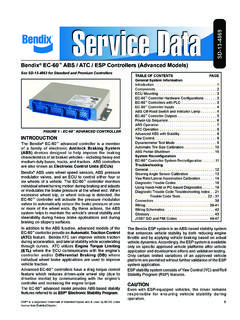
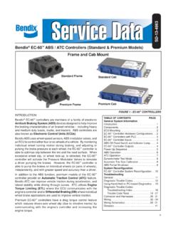
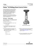
5 Components with stripped threads or damaged parts should be replaced rather than repaired. Do not attempt repairs requiring machining or welding unless specifi cally stated and approved by the vehicle and component manufacturer. Prior to returning the vehicle to service, make certain all components and systems are restored to their proper operating condition. For vehicles with Automatic Traction Control (ATC), the ATC function must be disabled (ATC indicator lamp should be ON) prior to performing any vehicle maintenance where one or more wheels on a drive axle are lifted off the ground and moving. The power MUST be temporarily disconnected from the radar sensor whenever any tests USING A DYNAMOMETER are conducted on a vehicle equipped with a Bendix Wingman system. You should consult the vehicle manufacturer's operating and service manuals, and any related literature, in conjunction with the Guidelines 2 - Typical System Schematics with Bendix SR-5 Trailer Spring Brake ValveTWO-TANK SYSTEMTRAILER SERVICESERVICE/ Spring Brake RESERVOIRTRAILER SUPPLYSERVICE RELAY VALVESERVICE/ Spring Brake RESERVOIRBENDIX SR-5 VALVEONE-TANK SYSTEMTRAILER SERVICESERVICE/ Spring Brake RESERVOIRTRAILER SUPPLYSERVICE RELAY VALVESR-5 VALVE4 Figure 3 - Charging Below 70 PSITRAILER SUPPLYSPRING Brake CHAMBERTRAILER SERVICE PISTONDELIVERYOPERATIONCHARGING BELOW 70 PSI (SEE FIGURE 3)Air flows through the Trailer supply line, enters the Bendix SR 5 Valve Trailer supply port, and moves the control piston.
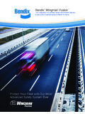
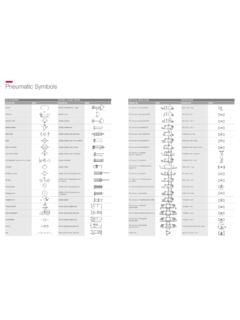
6 The control piston contacts the control inlet/exhaust Valve , sealing off the piston s exhaust piston travel continues, the control inlet Valve opens. Air acting on the control piston also flows through passage A, unseating check Valve B, and flowing past the open control inlet Valve . This air flows into the Spring Brake cavities, releasing the Spring ABOVE 85 PSI (SEE FIGURE 4)Air pressure acting on the control piston and flowing through passage A also acts on pressure protection ( Valve C). At approximately 85 psi, Valve C opens. This allows the air to flow past check Valve D and charge the Trailer reservoir(s). The Trailer braking system is now in the normal run mode. Service braking occurs through the Trailer service relay ATRAILER SERVICECHECK Valve BSERVICE/ Spring Brake RESERVOIR CONNECTIONSERVICE RELAY VALVECHECK Valve DFigure 4 - Charging Above 85 PSICONTROL PISTONPRESSURE PROTECTION Valve CSPRING Brake CHAMBERTRAILER SERVICE ATRAILER SERVICECHECK Valve BSERVICE/ Spring Brake RESERVOIR CONNECTIONSERVICE RELAY VALVEDELIVERYCHECK Valve D5 Figure 6 - Park Release with Trailer ChargedFigure 5 - Park ApplicationTRAILER SUPPLYSPRING Brake CHAMBERTRAILER SERVICE PISTONEXHAUST PASSAGETRAILER SERVICECHECK Valve BSERVICE/ Spring Brake RESERVOIR CONNECTIONSERVICE RELAY VALVEPRESSURE PROTECTION Valve CSPRING Brake CHAMBERTRAILER SERVICE ATRAILER SERVICECHECK Valve BSERVICE/ Spring Brake RESERVOIR CONNECTIONSERVICE RELAY VALVECHECK Valve DCONTROL PISTON Trailer SUPPLYCHECK Valve FCHECK Valve DPARK APPLICATION (SEE FIGURE 5)
7 To park the Trailer , either the Trailer air supply Valve or the system park control Valve (in the tractor) is actuated. This vents the Trailer supply line. The control piston, no longer under supply pressure, is moved by air pressure on its delivery side. This allows the control piston to move to the exhaust position. The control inlet Valve closes and the exhaust Valve opens, allowing air from the Spring brakes to exhaust through the passage in the control piston and apply the brakes. Check valves B and D close, preventing Trailer reservoir air pressure loss through passage RELEASE WITH Trailer CHARGE (SEE FIGURE 6)To release a park application with the Trailer charged, the Trailer supply Valve (in the cab) is actuated. Air flows through the Trailer supply line and enters the Bendix SR 5 Valve Trailer supply port. With a minimum of 55 psi on the control piston, the piston will move, sealing its exhaust passage. As piston travel continues, the inlet Valve opens.
8 Reservoir air (approx. 110 psi) then flows through check Valve F, past the open inlet, and out to the Spring Brake chambers to release the that pressure protection Valve C will open if Trailer supply air is greater than 70 psi. But check valves B and D will not open unless release pressure from the tractor exceeds Trailer reservoir (SEE FIGURE 7)The Bendix SR 5 Valve has an optional anti compounding feature. A single check Valve in the SR 5 Valve cover prevents Brake compounding (simultaneous Spring Brake and service Brake application), which creates an extra load on foundation Brake a Trailer service application is made and, simultaneously, a park application is made, air in the service line flows through single check Valve E in the SR 5 Valve cover. Pressure is maintained on the control piston, while air also flows out the Trailer supply line and exhausts through the tractor protection control.
9 Future compounding is prevented by the closed tractor protection 7 - Optional Anti-CompoundingANTI-COMPOUNDING LINESPRING Brake CHAMBEREXHAUSTTRAILER SERVICECHECK Valve FSERVICE/ Spring Brake RESERVOIR CONNECTIONSERVICE RELAY VALVETRAILER SUPPLYCHECK Valve EDELIVERYFAILED Trailer RESERVOIR (SEE FIGURE 8)Should Trailer reservoir pressure be lost, Trailer service braking is no longer available. Pressure protection Valve C will close at approximately 70 psi (minimum), retaining air pressure in the Trailer supply air held by the pressure protection Valve will continue to hold the control piston s inlet Valve open, supplying air to the Spring brakes. Thus, no automatic Spring Brake application occurs. However, Trailer supply line air can be used to apply and release the Trailer Spring brakes MAINTENANCEI mportant: Review the Bendix Warranty Policy before performing any intrusive maintenance procedures. A warranty may be voided if intrusive maintenance is performed during the warranty two vehicles operate under identical conditions, as a result, maintenance intervals may vary.
10 Experience is a valuable guide in determining the best maintenance interval for air Brake system components. At a minimum, the SR 5 Valve should be inspected every 6 months or 1500 operating hours, whichever comes first, for proper operation. Should the SR 5 Valve not meet the elements of the operational tests noted in this document, further investigation and service of the Valve may be 8 - Failed Trailer ReservoirPRESSURE PROTECTION Valve CSPRING Brake CHAMBERTRAILER SERVICE RESERVOIREXHAUSTTRAILER SERVICECHECK Valve BSERVICE/ Spring Brake RESERVOIR CONNECTIONSERVICE RELAY VALVETRAILER SUPPLYSERVICE CHECKS1. Remove any accumulated contaminants. Visually inspect the Valve s exterior for excessive corrosion or physical damage. Repair/replace the Bendix SR 5 Valve as Inspect all air lines connected to the Valve for signs of wear or physical damage. Repair/replace as Test air line fittings for excessive leakage and tighten or replace as AND LEAKAGE TESTSC heck the tractor dash gauge against a gauge known to be accurate before performing these tests.