Transcription of SD-23-7541 Bendix ADB22X , ADB22X -V & ADB22X LT Air …
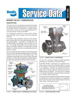
1 1 Bendix ADB22X , ADB22X -V & ADB22X - LT Air disc BrakesSD-23-7541 SECTION ONE: AIR disc brake DESCRIPTIONB endix ADB22X , ADB22X -V, and ADB22X -LT air disc brakes (ADB) use a floating caliper design to provide foundation braking on all axles of heavy commercial vehicles, buses, and trailers. Bendix air disc brakes provide safety and performance as well as ease of service. The ADB22X disc brakes mount to the axle's anchor plate (torque plate) using fasteners that are installed parallel to the axle, while the anchor-plate fasteners used for the Bendix ADB22X -V air disc brakes install at right angles to the axle. The ADB22X -LT air disc brake is designed for trailer with or without a combination spring brake unit, these brakes may also include optional wear sensors and wear diagnostic 1 Bendix ADB22X Air disc Air disc brake IdentificationLocate the identification label near the guide pin housing.
2 See below for information about the label fields used. Figure 2 Typical Part Number Label LocationBendix Part NumberSerial Part NumberFigure 3 Part Number Label InformationSection OneSection Description .. Air disc brake Identification.. Rotor Identification .. Wear Sensor Identification .. Operation .. brake Release and Adjustment .. 5 Label2 WARNING: Not all wheels and valve stems are compatible with Bendix air disc brakes . Use only wheels and valve stems approved by the vehicle manufacturer to avoid the risk of valve stem shear and other compatibility issues. WARNING: AVOID CREATING DUST. POSSIBLE CANCER AND LUNG DISEASE Bendix Commercial Vehicle Systems LLC does not off er asbestos brake linings, the long-term aff ects of some non-asbestos fi bers have not been determined.
3 Current Occupational Safety and Health Administration (OSHA) Regulations cover exposure levels to some components of non-asbestos linings, but not all. The following precautions must be used when handling these materials. Avoid creating dust. Compressed air or dry brushing must never be used for cleaning brake assemblies or the work area. Bendix recommends that workers doing brake work must take steps to minimize exposure to airborne brake lining particles. Proper procedures to reduce exposure include working in a well-ventilated area, segregation of areas where brake work is done, use of local fi ltered ventilation systems or use of enclosed cells with fi ltered vacuums. Respirators approved by the Mine Safety and Health Administration (MSHA) or National Institute for Occupational Safety and Health (NIOSH) should be worn at all times during brake servicing.
4 Workers must wash before eating, drinking, or smoking; shower after working, and should not wear work clothes home. Work clothes should be vacuumed and laundered separately without shaking. OSHA & EPA Regulations regarding testing, disposal of waste, and methods of reducing exposure for asbestos are set forth in 29 & 40 Code of Federal Regulations & , respectively. These Regulations provide valuable information which can be utilized to reduce exposure to airborne particles. Safety Data Sheets on this product, as required by OSHA, are available from Bendix . Call 1-800-247-2725 and speak to the Tech Team or email WARNING: If pads or rotors show signs of premature wear or failure, verify the brake chamber is sized appropriately for the application.
5 An over-sized brake chamber can result in excessive force being applied to the brake pads and rotors. Additionally, under-sized brake chambers can result in too little braking force being applied to the brake and could increase the time and distance needed to stop the vehicle. See the table on the right for brake chamber Air disc BrakeADB22X ADB22X -LTMax. permissible Bendix cylinder size Service brake systemT24T18 Parking brake systemT24/24 HFL1T18/24 DDSBSERVICE DATA INDEXS ection One: Air disc brake 1 Safe Maintenance Description .. Air disc brake Identification .. Rotor Identification .. Wear Sensor Identification .. Operation .. brake Release and 5 Section Two: Preventive Maintenance Schedule and Wheel-On Inspections Preventive brake Pad and Rotor Running Clearance Quick 10 Section Three: Troubleshooting Procedure Flowchart.
6 11 Section Four: Wheel-Off Maintenance Wheel-Off Running Clearance Test .. Adjuster Mechanism Inspection .. Inspect The brake Pads .. Inspect The Guide Pin Bearing Tappet And Boot Assembly Inspection .. 19 Section Five: Maintenance Kits And Procedures .. Maintenance Kits .. General Information About Bendix Air disc brake Air disc brake Dust Shield Pad Caliper/Carrier/Actuator Assembly .. Spring or Service brake .. 30 Tappet & Boot Assemblies and Tappet Inner Seal Replacement .. Guide Pin and Boot Assemblies .. Bendix Splined disc Hub 43 Section Six: U-Shape Rotor 45 Contacting Bendix .. Rotor IdentificationSee Figure 4 to help you identify which type of rotor is used on the axle being inspected.
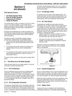
7 Note that the maintenance inspection procedure will depend on the type of rotor installed. Conventional RotorBendix Splined disc RotorFigure 4 Rotor IdentificationCAUTION: Rotors may not be mixed on a single axle: axles are only permitted to have all conventional or all Bendix Splined disc brake Wear Sensor IdentificationSee Figure 5 for the electronic wear sensor that may be OperationBendix air disc brakes convert air pressure into braking force. (See Figure 6.) When the vehicle brakes are applied, air enters the service brake chamber through the supply port, applying pressure within the diaphragm. The pressure expands the diaphragm applying force to, and moving, the pressure plate and pushrod forward. The pushrod acts against a cup in the internal lever which pivots on an eccentric bearing moving the bridge.
8 Moving against a return spring, the bridge transfers the motion to two threaded tubes and tappets, which move the inner brake pad. The inner brake pad (from its normal position of having a running clearance between it and the rotor) moves into contact with the brake rotor. Further movement of the bridge forces the caliper sliding on two stationary guide pins away from the rotor. That, in turn, pulls the outer brake pad into the rotor. The clamping action of the brake pads on the rotor applies braking force to the ..101 Cable to Electrical Protection Plate ..104 Cable Guide - Not Shown (two designs) .105 Mounting the instruction sheet included with wear indicator kits for installation 5 Electronic Wear Indicator ComponentsVersion 1 Version 2104 Cable Protection Plate104 Cable Protection Plate101 Sensor106 Mounting Pin103 Cable to Electrical Supply 101 Sensor103 Cable to Electrical Supply Electronic Wear Sensor (if installed)
9 5 Supply Port Return Spring PushrodLeverOuter brake PadInner brake PadRotor Service brake ChamberBridgePressure PlateDiaphragmEccentric Bearing Figure 6 Sectional View Showing brake brake Release and AdjustmentWhen the vehicle brakes are released, the air pressure in the service brake chamber is exhausted and the return springs in the chamber and the bridge return the air disc brake to a neutral, non-braked position. To maintain the running clearance gap between the rotor and the brake pads over time, the non-braked position is mechanically adjusted by a mechanism in the caliper. The adjustment mechanism operates automatically whenever the brakes are activated, to compensate for rotor and brake pad wear and to keep the running clearance constant.
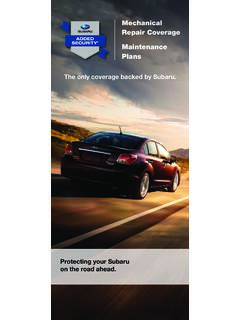
10 During pad or rotor maintenance, the technician manually sets the system s initial non-braked position. The total running clearance (the sum of clearances on both sides of the rotor) should be between to in. ( to mm).6 Figure 7 Sectional Views19 Lever20 Eccentric Bearing 43 Bolt17 Bridge 27 Spring2 Carrier24 TurningDevice33 Wear Sensor22 InnerSeal16 Threaded Tube161 Tappet13 Tappet and Boot Assembly18/1 Spring brake or18/2 brake Chamber46 Rotor12 Pad Assembly12 Pad Assembly6 Guide Sleeve 2 Carrier4 Guide Pin9 Inner Boot58 Ring39 Caliper Bolt68 CapBushing1 Caliper5 Guide Pin13 Tappet and Boot Assembly23 Adjuster Unit26 Spring Clip27 Spring7 Brass Bushing9 Inner Boot10 Cap12 PadAssembly16 Threaded Tube22 Inner Seal32 Chain Wheel161 Tappet Bushing61 Shear Adapter58 Ring45 Washer 40 Caliper Bolt Top Sectional ViewShort Caliper Bolt Sectional ViewSide Sectional View17 Bridge11 Pad Retainer30 Chain 44 Pad Retainer Pin37 Adjuster Cap7 Figure 8 Exploded