Transcription of SDS M2000-148 FREE FLOAT STEAM TRAP - TLV - …
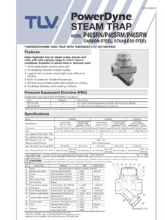
1 SDS M2000-148 . free FLOAT . STEAM TRAP. MODEL J3X. free FLOAT STEAM TRAP WITH THERMOSTATIC AIR VENTING. Features A reliable and durable ductile cast iron or cast iron STEAM trap with tight shut-off for use on small-size process equipment. 1. Self-modulating free FLOAT provides continuous, smooth, low velocity condensate discharge as process loads vary. 2. Only one moving part , the free FLOAT , prevents concentrated wear and provides long maintenance- free service life. 3. Thermostatic capsule (X-element) with fail open . feature vents air automatically until close-to- STEAM temperature. 4. Built-in screen with large surface area ensures extended trouble- free operation. 5. Easy, inline access to internal parts simplifies cleaning and reduces maintenance costs.
2 Specifications Model J3X JF3X. Connection Screwed Flanged Size (mm) 15, 20, 25. Orifice No. 2, 5, 8, 10, 21 2, 5, 8, 10, 16. Maximum Operating Pressure (MPaG) PMO , , , , , , , , Maximum Differential Pressure (MPa) PMX , , , , , , , , Minimum Operating Pressure (MPaG) Maximum Operating Temperature ( C) TMO 220. Subcooling of X-element Fill ( C) up to 6. Type of X-element B. PRESSURE SHELL DESIGN CONDITIONS (NOT OPERATING CONDITIONS): 1 MPa = kg/cm2. Maximum Allowable Pressure (MPaG) PMA: (J3X), (JF3X). Maximum Allowable Temperature ( C) TMA: 220. To avoid abnormal operation, accidents or serious injury, DO NOT use this product outside of the specification range. CAUTION Local regulations may restrict the use of this product to below the conditions quoted.
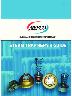
3 No. Description Material JIS ASTM/AISI* !9 !8. J3X Ductile Cast Iron FCD450 A536 !0 !5. q Body JF3X Cast Iron FCV410 A842 w !2. w Cover Ductile Cast Iron FCD450 A536 !7 !3. eF FLOAT Stainless Steel SUS316L AISI316L o !6. r Orifice Holder Plug Carbon Steel S25C AISI1025. t MR Orifice Plug Gasket Fluorine Resin PTFE PTFE. !4. yR Orifice . u MR Orifice O-Ring Ethylene Propylene Rubber EPR D2000CA. iR Screen inside/outside Stainless Steel SUS430/304 AISI430/304 i o MR Cover Gasket Fluorine Resin PTFE PTFE !1. !0 Nameplate Stainless Steel SUS304 AISI304. !1 R FLOAT Cover Stainless Steel SUS304 AISI304 e !2 R X-element Guide Stainless Steel SUS304 AISI304 @0 q r !3 R X-element Stainless Steel !4 R Spring Clip Stainless Steel SUS304 AISI304 t !5 R Air Vent Valve Seat Stainless Steel SUS420F AISI420F.
4 !6 Connector Stainless Steel SUS416 AISI416. !7 Cover Bolt Carbon Steel S45C AISI1045 y !8 Plug Carbon Steel S25C AISI1025 u !9MR Plug Gasket Fluorine Resin PTFE PTFE Optional lock release valve LR3. @0 Drain Plug Gasket** Soft Iron SUYP AISI1010 available for special applications. @1 Drain Plug** Carbon Steel S25C AISI1025. * Equivalent ** Option Copyright Replacement kits available: (M) maintenance parts, (R) repair parts, (F) FLOAT Dimensions r J3X Screwed J3X Screwed* (mm). Size L H H1 W Weight (kg). L W. 15 75 130. 20 120 73 80 25 137 75 * Rc(PT), other standards available H. H1. r JF3X Flanged JF3X Flanged (mm). L L. Weight*. Size ASME Class H H1 (kg). 125FF (150RF) 250RF (300RF). (15) 175 175 127 79 (20) 195 195 133 89 H. 25 203 215 215 219 140 91 H1.
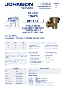
5 ( ) No ASME standard exists for cast iron; machined to fit steel flanges Class 125 FF can connect to 150 RF, 250 RF can connect to 300 RF. Other standards available, but length and weight may vary * Weight is for Class 250 RF / 300 RF. Discharge Capacity Differential Pressure (kg/cm2). 21. 1 2 3 5 8 10 16 20. 800. 5 8. 600 2 10 16 21. Discharge Capacity (kg/h). 400. 300. 200. 100. 80. 60. Differential Pressure (MPa). 1. Line numbers within the graph refer to orifice numbers. 2. Differential pressure is the difference between the inlet and outlet pressure of the trap. 3. Capacities are based on continuous discharge of condensate 6 C below saturated STEAM temperature. 4. Recommended safety factor: at least DO NOT use traps under conditions that exceed maximum differential pressure, CAUTION as condensate backup will occur!
6 Copyright SDS M2000-148 Rev. 2/2017. Products for intended use only. (O) Specifications subject to change without notice.