Transcription of Sealing SenSe
1 96 September 2010 pumpS & SyStemSThis is the second of a four-part Sealing SenSe series that provides guidance on best practices to mini-mize the size of the Sealing system energy footprint. The first article discussed energy losses from the interaction between the seal faces of a mechanical seal. This article will discuss the thermal energy needed to maintain a suitable temperature for the interfacial lubricating fluid in high-tem-perature Fluid FlushThe reliability and emission performance of any mechanical seal depends on the ability to maintain a stable fluid film between the faces. The three types of mating face lubrication regimes were discussed in the August 2010 Sealing SenSe .
2 For most applications, it suffices to provide a small amount of process fluid flow as flush to remove the seal-face-gener-ated heat and lubricate the faces. The minimum flush flow rate is based on a 10 deg C (18 deg F) maximum allowable process fluid temperature rise. This flush-flow rate represents a small energy loss because the process fluid used for the flush needs to be re-pumped from suction back to discharge. These systems do not rely on the cooling of the fluid, so they consume an insignificant amount of energy compared with the total energy footprint of the pumping system . API Piping Plans 1,11,12,13, 14 and 31 are examples of Sealing systems that use process fluid without cooling as flush.
3 They are applicable to single seals and the process side seal of a dual, unpressurized seal. The maximum recommended operating temperature of these piping plans will depend on the process fluids lubri-cating qualities at operating conditions such as seal chamber pressure and pump speed. Other considerations include the temperature limits of the secondary seals and the potential consequences of normal and transient leakage rates, or a major leak (seal failure) to the surrounding environment and the safety of personnel. External cooling The small energy footprint for operating seals at high tem-perature has been recognized, but in some cases, cooling of the process fluid is needed to achieve acceptable reliability, emission and safety targets.
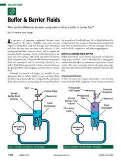
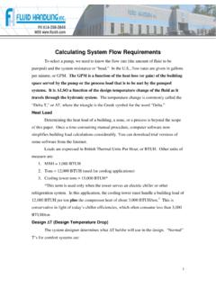
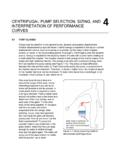
4 Historical data of seal OEMs show that an annual energy savings of approximately What is the Sealing system Energy Footprint for Controlling Process or Barrier Fluid Temperature?Second of four partsthis month s Sealing SenSe was prepared by FSA member eric VanhieFigure 1. API Piping Plans 21 and the voice of the fluid Sealing industrySealing SenSepumpS & SyStemS September 2010 97kW per 25 mm (1 in.) of shaft size can be realized for every 38 deg C (100 deg F) of cooling requirements that can be removed from the seal cavity. Many high-temperature applications are found in refineries, power plants and some chemical processes. The most common Sealing systems to incorporate cooling of the process fluid are API Piping Plans 21 and 23.
5 API Piping Plans 21 and 23In these plans, an external heat exchanger reduces the process fluid temperature considerably and provides a cool flush over the seal faces. This may be needed to protect against vapor for-mation, meet temperature limits of secondary Sealing elements, reduce coking or polymerizing of the leakage or improve the lubricating qualities of a process fluid such as hot water. The primary benefit of Plan 21 is a sufficient pressure dif-ferential to achieve the high flow rates needed to cool the seal. The drawback is that the cooler duty is high and the flush flow needs to be re-pumped to discharge, which may result in a sig-nificant energy foot 23 is the default for many hot water and hydrocarbon services in power plants and refineries.
6 The cooler duty is much lower than that for Plan 21 because it only removes the seal face generated heat and a small amount of heat soak from the process. The seal incorporates a pumping device that circulates the process fluid to the cooler and back to the seal chamber. The process fluid in the seal chamber is isolated from the hot process fluid with a throat bushing in the impeller area to minimize the heat soak loss. Heat soakHeat soak is a source of heat flow into or out of the fluid that lubricates the seal faces. It is the result of the temperature differ-ence between the seal chamber and the environment surround-ing the seal chamber. Calculating the heat soak loss is a complex matter because of the many variables involved.
7 Mechanical seal standard API 682 provides a simplified method for estimating this heat loss. The cooling capacities of the heat exchangers that are used in Plan 23 are 6 and 36 kW, which cover the majority of all high-temperature applications. From an energy standpoint, Plan 23 has a smaller footprint than Plan 21, but the process fluid cannot contain many solids or be too viscous, sticky or have polymerizing tendencies. Dual sealsSealing systems for dual seals require an external cooler to con-trol the barrier fluid temperature within a specified range, with the maximum at 80 deg C (176 deg F) for many barrier fluids. The thermal loss due to heat soak may become significant for process temperatures above 150 deg C (302 deg F).
8 The sources of energy consumption in these auxiliary systems include the circle 177 on card or go to 179 on card or go to %\ 'HVLJQ 1-800-238-7474 Dollars Going to Waste?Control Dollars Going to Waste?Providing industrial controls and monitoring products for over 30 years, Macromatic is making waves in the Water/Wastewater market with quality products like:Customer-oriented application solutions include standard, modified standard, and custom engineered products, for new design project requirements, replacement parts, OEM and MRO RelaysPump Seal Failure RelaysIntrinsically Safe RelaysPhase Monitor RelaysCurrent and Voltage Monitor RelaysPump up your productivity withMacromatic Ensuresprotectionfromarc flash SimplifiesNFPA70E complianceQualifiedtechnicianscan safelydeenergizeand service todeenergizeDeadFrontSafetyShutter98 September 2010 pumpS & SyStemSFSA Sealing Sensepumps and motors to create the flow and pressure in the Sealing system .
9 The heat removed by cooling water through heat exchangers and additional system heat removed above and beyond the seal chamber heat load because of system design. Each service is somewhat different and can best be esti-mated by your local seal manufacturer. The maximum cooling capacity of systems for dual seals is 8 kW for Plans 52 and 53A and up to 36 kW for Plans 54 and 53B. Systems for gas-lubricated seals consume an insignificant amount of energy as described in the August Sealing SenSe . Air coolingThis is an effective method for reducing the energy footprint of Sealing systems in general. The elimination of cooling water reduces the cost to operate the seal and pump. The drawbacks of air cooling include its limited capacity and typical restriction to outdoor installations.
10 Another method for eliminating the cooling water is to use product cooling. In this case, the process fluid is circulated through a coil in the barrier fluid reservoir or heat exchanger to remove the heat from the seal. This method is limited to process temperatures up to 50 deg C (122 deg F), and the fluid must be free of solids. The energy required to re-pump the process fluid back to discharge must be considered as the flow rates may be fairly high in this scenario. Conclusions1. The energy footprint for controlling process or barrier fluid temperature can be estimated for any flush plan application. Meaningful comparisons can be made to determine the most energy-efficient system . 2. Reliability, emissions and safety aspects of the seal must be considered during the evaluation and selection process.