Transcription of SEALING SENSE
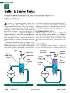
1 Are the symptoms, causes, and correctiveactions for failure of mechanical seals by thermal attack? symptom of thermal attack is the appear-ance of fine-to-large radial cracks that emanate fromthe center of the metal or ceramic ring. Character-ized asheat checking,these cracks act as cuttingedges on the carbon-graphite and other seal facematerials, and the consequent scraping action rapid-ly wears out the causes of heat checking include: (1)insufficient lubrication; (2) vaporization at the sealfaces; (3) inadequate cooling; and (4) excessive pres-sures and velocities. Any one or a combination ofthese factors can result in higher friction and heat atthe seal faces. The excessive thermal stresses thatdevelop will result in fine Actions include: Checking operating conditions to ensure theyare within the prescribed limits for the seal .
2 Confirming adequate coolant flow at the sealfaces to carry away seal -generated heat; guide-lines are that (a) the temperature rise of thefluid flowing through the seal cavity should notexceed 40 F (22 C); and (b) pressure of theseal cavity product should be maintained 25 PSI ( bar) above the vapor pressure of theseal cavity fluid to avoid vaporization. Checking that the seal is not overloaded so thata thrust bearing or thrust collar in the equip-ment becomes damaged or inoperative, therebycreating excessive seal face loads. Upgrading to seal face materials with higherpressure-velocity (P-V) limits and resistance toheat checking such as tungsten carbide or sili-con carbide. (P-V is the pressure (PSI) at theseal faces, multiplied by the velocity (ft/min) ofthe outside diameter of the seal face.)
3 Consulting the manufacturer to obtain reviseddimensions that will reduce the hydraulic loadat the seal faces to provide a lower P-V for thesame face materials. Verifying ample cooling and lubrication at theseal , puffing, and blowing of vapors at theseal face, known asvaporization,is another symp-tom of thermal attack that results in excessive leak-age and damage. If vaporization doesn t cause fail-ure, it usually shortens seal life and impairs seal per-formance. Inspection of the seal faces usually showschipping at the inside and outside diameters, andpitting over the entire occurs when heat at the seal facescannot be adequately removed, and the liquidbetween them rapidly evaporates or flashes. It alsocan be caused by operating the seal too near theflash temperature and flash pressure of the productin the seal cavity.
4 Other operating conditions thatcause vaporization include: (1) excessive pressure forthe seal ; (2) excessive seal face deflection; (3) inade-quate cooling and lubrication of the may be an indication that a seal flushhas become inoperative, or that cooling water flowto a heat exchanger has been shut off or Actions include: Improving circulation and cooling at seal faces. Assuring that the seal is operating at tempera-tures and pressures well below the flash condi-tions of the product in the seal cavity; guide-lines are that the operating temperature andpressure at the seal should be at least 25 F (14 C) and 25 PSI ( bar) below the flash tem-perature and flash pressure of the product in theseal cavity. Checking seal design to assure operation withinpressure and speed limits.
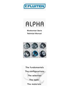
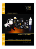
5 Consulting seal manufacturer for recommenda-tions on reducing self-generated another symptom of thermal attackcharacterized by small circular sections that appearraised on the carbon seal faces. This condition isDECEMBER 2004 & SYSTEMS18 SEALING SENSEFrom the voice of the fluid SEALING industryFigure 1. Ceramic ring with typical heat checking cracksDEC04 PUMPS&SYSp18-19 11/17/04 9:34 PM Page 18best observed by using an optical flat or lightly lap-ping the seal faces. These blisters separate the sealfaces during operation and cause high leakage usually occurs in three stages: Stage I Small raised sections will appear at the seal faces;Stage II Cracks will appear in the raised sections,usually in a starburst pattern; Stage III Blisters willbe pulled out, leaving voids in the seal exact cause of blistering is still not welldefined.
6 The best explanation is that high viscosityfluids, such as SAE #10 oils, penetrate the intersticesof the carbon seals over time. When the seals heatup, the oil is rapidly driven from the often occurs in seals that frequently startand stop in high viscosity Actions include: Reducing the viscosity of the fluid in the sealcavity by substituting a new fluid or by increas-ing the fluid s temperature. Eliminating frequent starts and stops of equip-ment with mechanical seals. Substituting a non-porous seal face materialsuch as tungsten carbide, silicon carbide orbronze for the carbon-graphite. Checking cooling and circulation to the sealfaces; improper cooling and circulation willmake seals more susceptible to similar to blistering, but occurs onsurfaces away from the seal face, such as the outsidediameter and the back of the seal .
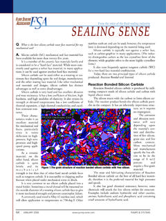
7 Like blistering,spalling is caused by excessive thermal stresses in acarbon-graphite seal . Unlike blistering, however,spalling seems to occur with virtually any fluid, andis the result of moisture suddenly being driven offwhen the seal is overheated. It is almost always dueto dry running of the seal . If seal parts are heavilyspalled, it s a good indication that the equipmentwas allowed to run dry for an extended period avoid dry running of a mechanical seal , apressure or load switch should be added to theequipment. Or, an alternative SEALING methodshould be supplied, such as a double seal incorpo-rating a thermal-convection or , elastomer O-ringsharden, crack andbecome very brittle. PTFE secondary seals willharden, tend to discolor (becoming bluish-black orbrown), show signs of cold flowing, or take theshape of the secondary seal is generally due to inadequatecoolant flow in the seal cavity.
8 It also can result fromexcessive temperatures, or simply by an incorrectmaterials selection. If O-ring overheating is noted:(1) check coolant flow in the seal cavity area, includ-ing the lines for blockage, and heat exchangers forbuildup of scale; (2) increase cooling. If the temper-atures are still too high for a given elastomer sec-ondary seal , consider a metal bellows seal with high-er temperature Month: The introduction of a new software toolfor calculation of mechanical seal Life Cycle & DECEMBER 200419 FSA s updatedMechanical seal Handbookisnow available. Reflecting advances in sealingtechnology and application, it provides valuableinformation on the selection and use of the mostpopular mechanical seal designs, configurationsand include Safety, Selection, Designand Classification, Environmental Controls,Installation, and Troubleshooting.
9 A comprehen-sive Materials Selection Guide provides guidancein the proper selection of metal components, facematerials, and secondary seals. An extensiveGlossary of terms takes the mystery out of thelanguage of mechanical seals, and includes asimple explanation of balance ratio, includingcalculation formulae. Line and photographicillustrations complement this easy-to-read 48-page Seals Handbookis a valuablereference for process industries personnelinvolved in plant maintenance, operations, relia-bility, and engineering. It also is useful for design-ers of OEM rotating equipment, and for distrib-utor personnel charged with technical support fortheir process industry per single copy is $ , with volumediscounts available. To purchase, please 2.
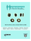
10 Carbon-graphite seal exhibiting spallingDEC04 PUMPS&SYSp18-19 11/17/04 9:34 PM Page 19