Transcription of SEALING SENSE
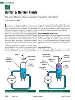
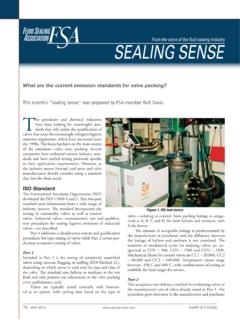
1 From the voice of the fluid SEALING industry SEALING SENSE . How do I determine bolt torque for flanged connections? C. ontrolling the load is essential to ensuring the gas- keted joint will seal properly. Previous SEALING SENSE articles have examined the types of gaskets to use, how flange finish affects gasket SEALING and major pitfalls to avoid to properly assemble a gasketed joint. However, regardless of the type of gasket, controlling the load is prob- ably the most important criteria for getting a gasketed joint to seal. A big problem is the load on the gasket cannot be measured directly and easily during installation. Figure 1. Forces on a bolted connection However, applied torque on the flange bolts can be measured and controlled and is one of the most frequently twice the axial force as a nut factor. Small changes in the used methods to control gasket load. This article explores nut factor can result in large changes in the load experienced bolt torque and the major considerations for converting by the gasket.
2 This illustrates the need for a well-lubricated measurable bolt torque into the gasket load necessary to seal bolt, nut and washer. a flanged connection. Forces on a Bolted Connection Bolt Torque As described above, the bolts act like springs pulling the Torque is the turning force measured in foot-pounds (ft-lb) flanges together. They need to be stretched enough to keep or inch-pounds (in-lb) applied to tighten (turn) the nut the load on the gasket as the system is pressurized and as pres- on a bolt. Torque can be measured during flange assembly sure and temperature cycle during normal usage. Additional with a properly calibrated torque wrench. In a bolted flange, loading above the minimum load required to seal will give the applied torque generates the axial load in the bolt. The the bolted joint flexibility to absorb these load changes and bolt acts like a spring. Tightening the nut stretches the a safety margin to maintain the seal as these system forces bolt, which increases the load on the gasket.
3 The relation- fluctuate. ship between torque, the turning force, axial bolt force and Bolt yield strength is a measure of the load required gasket load can be expressed by the simplified formula: to stretch the bolt to its maximum length or stretch and still allow it to spring back to its original length. If the bolt T= (k f d)/12 is overstretched and is loaded beyond its yield strength, the bolt will not spring back when the load is removed. Where: Overloading bolts can cause them to stretch beyond their T = Torque in ft-lb yield strength and actually result in lower loads exerted on k = Dimensionless nut factor the gasket, after additional external and application loads are f = axial force in pounds applied to the tightening of the bolts will d = Nominal bolt diameter in inches not necessarily increase gasket load or stop a gasketed joint leak, and may lead to bolt failure. The nut factor is a modified friction factor, but a nut The bolt may also lose its compressive load if it is not factor involves more than just friction.
4 It is more of a multi- stretched enough and the system relaxes beyond the amount plier in total, taking into account many other load losses. the bolt has been stretched. It is often recommended that a If the same torque is applied, a nut factor would produce bolt be loaded to approximately 50 to 60 percent of its yield 88 JUNE 2008 PUMPS & SYSTEMS. strength to ensure the spring is stretched enough. However, by the internal fluid pressure trying to push the this recommendation should be tempered by the amount of flanges apart gasket stress and flange stresses generated; check to ensure that 2. Compress the gasket enough to hold it in place the applied load will not overload and damage the gasket or when the internal pressure is trying to penetrate the flange. through the gasket and/or gasket/flange SEALING Bolts come in a variety of grades, each with individual surfaces yield strength and properties. Proper bolt selection is critical 3. Maintain some residual load on the gasket after to the proper assembly of a bolted flange joint.
5 The hydrostatic load has unloaded the gasket, which involves the gasket factor m. Gasket Design Requirements We have a torque wrench to measure the torque during assem- The forces needed to compress the gasket for an effective bly and a formula to calculate the torque based on the gasket seal vary with the type and style of gasket, the degree of flange load, but what is the gasket load needed to generate a seal? The tightness, system fluid, as well as temperature and pressure. f, or force, portion from our torque equation is composed of The ASME m and y gasket factors determine the loads needed two major parts, as noted by the design rules for raised face on the gasket, but it is best to get a recommendation from the pipe flanges in the Boiler and Pressure Vessel Code. First is gasket manufacturer. Note: the m and y gasket factors often the force needed to compress and hold the gasket in place. listed are non-mandatory, minimum values, and do not nec- The load generated by the bolts has to compress the gasket essarily speak to the leak tightness of a given joint.
6 So it conforms to the flange surfaces, and to seat the gasket The Code Design equation utilized to determine a mini- into the flange. This involves the gasket unit seating load or mum seating load on the gasket is as follows: factor, y. Second is the combined force needed to: Wm2 = ( b G)y 1. Overcome the hydrostatic end forces generated Fluid SEALING Association SEALING SENSE is produced by the Fluid SEALING Association as Daikin America, Inc. part of our commitment to industry consensus technical educa- Donit Tesnit tion for pump users, contractors, distributors, OEMs and reps. Empak Spirotallic Mexicana SA de CV. This month's SEALING SENSE was prepared by FSA Members Mark The Flexitallic Group Pollock, Brian Hasha, Pasche Raty and Jim Lingenfelder. As a Garlock SEALING Technologies source of technical information on SEALING systems and devices, Gore & Associates, Inc. and in cooperation with the European SEALING Association, the FSA also supports development of harmonized standards in GrafTech International Holdings, Inc.
7 All areas of fluid SEALING technology. The education is provided John Crane in the public interest to enable a balanced assessment of the Lamons Gasket Co. most effective solutions to pump technology issues on rational Latty International total Life Cycle Cost (LCC) principles. Leader Global Technologies The Gasket Division of the FSA is one of five with a spe- Nippon Pillar Corp. of America cific product technology focus. As part of their mission, they develop publications such as the Metallic Gasketing Technical SGL Technic Polycarbon Division Handbook as well as joint FSA/ESA publications such as Slade, Inc. Guidelines for Safe Seal Usage Flanges and Gaskets and Gasket Teadit International Installation Procedures. These are primers intended to comple- Teijin Aramid USA, Inc. ment the more detailed manufacturer's documents produced Thermoseal Inc. by the member companies. Triangle Fluid Controls, Ltd. The following members of the Gasket Division sponsor YMT/Inertech, Inc. this SEALING SENSE series: PUMPS & SYSTEMS JUNE 2008 89.
8 The first combination of parameters is basically an effec- derive the hydrostatic end forces. These are calculated by tive gasket area based upon pi times a derived gasket width b, multiplying the pressure P by the effective internal area of which is different for different compression configurations and the gasket ( G2 /4) where G is the load diameter, which is gasket types, and G, which is a gasket load reaction diameter. typically around the midpoint of the compressed gasket area. The derivation of these values for all of the different gasket The second term in the above equation is the required residual types and flange compression configurations is beyond the gasket load. It is calculated by multiplying the pressure P by scope of this article, but can be found in product literature and an effective gasket area (2 b G) and then multiplying this in the Boiler and Pressure Vessel Code. load by the gasket factor m. In essence, a gasket with a higher Note that some manufacturers utilize a gasket area much m factor will require a higher residual load.
9 Closer to the actual area of gasket SEALING surface under com- The code anticipates higher installation bolt loads than pression as opposed to the effective area illustrated above, giving these design values as a safety factor against leakage under a much more conservative number. This will still comply with operating conditions and to allow for joint relaxation in opera- the Code, since the Code gives minimum loads. This area is tion. It anticipates the possible need for initial bolt loads that then multiplied by the gasket factor y, to obtain the load Wm2. may be much greater than the minimum design value, pro- The greater the y value, the larger the load required to seat vided that excessive flange distortion and maximum gasket the gasket. load capacities are taken into consideration. The second load consideration is a combination of two Consequently, nearly all flanges use considerably higher factors, the hydrostatic end load on the flanged joint and a load values for installation.
10 Installation loads are often more residual gasket load. This load is determined by the following than twice the minimum design loads. We recommend con- equation: tacting gasket manufacturers for their recommended installa- tion gasket loads. Wm1 = (( G2 P)/4) + (2 b G m P). Summary The first portion of this equation represents a term to The greater of the two values Wm1 or Wm2 will dictate the minimum required design bolt load. The minimum required bolt load divided by the number of bolts in the Make your life easy. Use Val-Matic. flange will determine the minimum f, or force, needed to use the torque No Special Tools Required equation. After calculating the torque, No epoxy seat adjustment or replacement ensure the bolts are not over-stretch- ing and exceeding their yield strength, or some predetermined design stress. easy =. Additionally, check to see if the bolts are stretched enough for them to compen- sate for creep, pressure and temperature cycling and other load losses. A detailed look at the torque and loading required to seal bolted flange joints can be found in John Bickford's book Gaskets and Gasketed Joints.