Transcription of SEALING SENSE
1 112 AUGUST 2008 PUMPS & SYSTEMSA lmost all centrifugal and rotary pumps require a seal-ing system to provide SEALING integrity of the drive shafts carrying the impellers and protect against pumped fl uid leakage and the environment outside of the wetted areas. These SEALING systems range from traditional braided materials packed around the shaft to complex mechanical seal systems used in many modern pumps. Throat BushingsPump Standard API-610 requires that the pump casing contain a seal chamber in which mechanical seals compliant with API-682 can be mounted. A common component in both of these specifi cations is the so-called throat bushing, which is defi ned as: A device that forms a restrictively close clearance around the sleeve (or shaft) between the (inner) seal and the impeller. The throat bushing can form a primary interface between the pump and the mechanical seal. According to the arrangement of the mechanical seal and the type of fl ush plan applied, such bushings are not always required.
2 When they are used, the details of their design and use can be lost in the API-610 and API-682 standards. Here is a look at throat bushings in more detail. FunctionAs its defi nition implies, the primary role of a throat bushing is to provide a restriction between the fl uid being pumped by the impeller and the mechanical seal area, so that fl ow is reduced or controlled. Such a fl ow restriction can be required in either direction; for instance, the restriction would stop the fl ow into the seal chamber to avoid particulate contami-nation of the chamber. When the mechanical seal fl ush plan uses processed fl uid either cooled, fi ltered or physically different from the pumped media the fl ow from the seal chamber into the pump may need to be controlled. Throat bushings must be designed to provide the optimum envi-ronment for both the mechanical seal and pump since the fl uid fl ow amount through a concentric annular restriction is proportional to the cube of the clearance and their axial CriticalFor pumps working at high pressures, fl uid pressure control in the seal chamber, which provides loads on the mechani-cal seal faces, is important and often requires a very small throat bushing clearance.
3 It is often debated how small the clearance should be. All parties agree that controlling the clearance between the shaft and throat bushing leads to increases in effi ciency and performance of both the pump and mechanical seal since the isolation provided can allow optimum operation of both the clearances between the throat bushing and the rotating element can often lead to an increased risk of contact between the two components, especially during times of start-up and any upset situations within the pump or mechanical seal. The interface materials should be able to tolerate such contact without problems, including: Galling or seizing of the two components, which can occur between metallic materialsParticulate generation, which could possibly upset the micron level gaps found in the mechanical seal interfacesHeat generation, which can increase the temperature of the seal chamberIn essence, the throat bushing must behave as a wear part, so its material selection must be considered in the same way as it s considered for a wear component within the pump.
4 In addition to the bearing requirement for a throat bushing, effects like fl uid erosion and thermal expansion differences between the pump, shaft and throttle bushing must also be CompositesWith micron levels of clearance between mechanical seal Where mechanical seals meet pumps: What is the next generation? From the voice of the fl uid SEALING industry SEALING SENSEPUMPS & SYSTEMS AUGUST 2008 113faces, high levels of vibra-tion in the pump system can often be problematic. The use of composite wear rings to reduce these vibrations and assist with Lomakin Effect support of the rotating compo-nents has proven an asset to mechanical seals when used with composite wear ring equipped pumps. Extending the use of com-posites into the mechani-cal seal area can also pro-vide similar benefi ts to those found in pumps. In Fluid SEALING AssociationSealing SENSE is produced by the Fluid SEALING Association as part of our commitment to industry consensus technical education for pump users, contractors, distributors, OEMs and reps.
5 This month s SEALING SENSE was prepared by FSA Member Craig Watkinson. As a source of technical information on SEALING systems and devices, and in cooperation with the European SEALING Association, the FSA also supports devel-opment of harmonized standards in all areas of fl uid SEALING technology. The education is provided in the public interest to enable a balanced assessment of the most effective solutions to pump technology issues on rational total Life Cycle Cost (LCC) Mechanical Seal Division of the FSA is one of fi ve with a specifi c product technology focus. As part of their educational mission, they develop publications such as the Mechanical Seal Handbook, a primer intended to complement the more detailed manufacturer s documents produced by the member companies. This handbook served as the basis for joint development of the more comprehensive Hydraulic Institute publication: Mechanical Seals for Pumps: Application Guidelines.
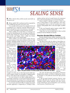
6 Joint FSA/ESA publications such as the Seal Forum, a series of case studies in pump performance, are another example as is the Life Cycle Cost Estimator, a web-based software tool for determination of pump seal total Life Cycle Costs. The SEALING Systems Matter initiative also was launched to support the case for choosing mechanical seals that optimize life cycle cost, safety and environmental following members of the Mechanical Seal Division sponsor this SEALING SENSE series:Advanced SEALING International (ASI)Ashbridge & Roseburgh Chesterton America, Performance Elastomers LLCE agleBurgmann Industries LPFlex-A-Seal, Flow Solutions Div. - Seal Group Garlock SEALING TechnologiesGreene, Tweed & , Vago de Mexico SA de CVJohn CraneKC AmericaLatty International Carbon AM&TNippon Pillar Corp. of AmericaParker Hannifi n Seal GroupPPC Mechanical SealsSEPCO - SEALING Equipment Products Co., Technic Polycarbon DivisionFigure 1. Typical pump and mechanical seal arrangement114 AUGUST 2008 PUMPS & SYSTEMSFSA SEALING Sensethe wetted area of the pumps, losses across the impeller eye can be reduced by closing the clearances between the wear gaps of the casing and impeller.
7 The ninth edition of API-610 fi rst rec-ognized the use of nonmetallic wear rings, particularly carbon fi ber reinforced Polyetheretherketone (PEEK) materials have reduced the wear ring gaps below those possible with more traditional metallic systems and have done so without compromising the risks of contact-induced problems. The typical single stage pump and mechanical seal arrangement in Figure 1 shows the pump wear parts, impel-ler (A) and hub (B). The fl ow arrows indicate the direction of the media fl ow with pumped and fl ush (green) and barrier (orange) fl uids in the system. The joint in the system is the throttle bushing (C) between the impeller and the mechanical seal chamber. As maintenance, reliability and effi ciency become ever more critical and the costs of pumps and mechanical seals con-tinue to increase, materials such as polymer composites can signifi cantly improve system design. Other areas where such light weight, wear-resistant mate-rials can provide tangible benefi ts within mechanical seals are:Internal circulating devices such as those required in Plan 23 fl ush plans, where inertial effects and closer clearances may provide benefi tsMechanical seal sleeves where thermal and centrifugal expansion of the supporting component must be matched with ceramic faces such as Silicon CarbideThrottle bushings located on the outboard of the mechani- cal seal to reduce the low leakages from the mechanical seal even further (see D in Figure 1)Labyrinth fl ow restrictors within the mechanical seal con- trolling and directing fl ow within the seal itselfConclusionThe next generation of materials where pumps meet mechani-cal seals may already be here in polymeric composites.
8 The pump and mechanical seal industries just need to recognize, defi ne and standardize these materials to realize their benefi Month: What are bolt torque considerations for valve pack-ing that ensure reliable performance?We invite your questions on SEALING issues and will provide best-effort answers based on FSA publications. Please direct your ques-tions to: sealingquestions@fl 26 ANSI/HI Pump Standards on 1 CDSearchable PDF filesHypertext links from indexes to:each Standardeach sectioneach pageEnabled:bookmarksannotationsprinting Select and purchase the right pumpIncrease pump & system reliabilityAccurately determine pump performanceTroubleshoot systems & operations Use them x18 The best way to use them on the jobsite!ANSI/HI PUMP STANDARDSON CD-ROMcircle 170 on card or go to 169 on card or go to Industry Coverage:Positive Displacement PumpsCentrifugal PumpsSpecialty & Other PumpsIndustrial ValvesPneumatic & Hydraulic ValvesCustom ResearchWhite PapersFrost & Sullivan, the Growth Consulting Company, partners with clients to accelerate their growth.
9 The company'sGrowth Partnership Services, Growth Consulting and Career Best Practices empower clients to create a growthfocused culture that generates, evaluates and implements effective growth strategies. Frost & Sullivan employs over 45years of experience in partnering with Global 1000 companies, emerging businesses and the investment communityfrom more than 30 offices on six continents. For more information about Frost & Sullivan s Growth Partnerships, us on the web at : ( )Email.