Transcription of SEALING SENSE
1 I seal vertical shafts with standard mechan-ical seals? seals are used to seal vertical shaftsevery day in industry. Selecting the correct designand piping plan will lead to longer seal life and morereliable equipment operation. Vertical-shafted fluidhandling equipment, though, presents slightly dif-ferent SEALING challenges than those found in othertypes of equipment. With vertical shafts, four variables influencechoice of seal design, seal face materials and pipingplan. They are: shaft speed, pressure, shaft size andequipment function. Shaft speed typically is characterized as low-,high- or extremely high-speed service. Low speed istypically defined as rotating at or below 300 RPM;high speed as 300 to 3700 RPM, and extremelyhigh speed as above 3700 RPM.
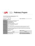
2 Shaft size also is an important SEALING consider-ation. The seal's velocity is defined as the speed of apoint at the center of the narrow seal face (or thecorresponding wide face, if it rotates) and the dis-tance that point travels in a given time units identify this velocity as surface feetper minute. The diameter of the shaft, at thispoint, is converted to the circumference of its pathduring rotation and then multiplied by the numberof revolutions per minute. Smaller-diameter shaftswill have a lower velocity, while larger shafts at thesame speed will experience a higher velocity giventhe same rotational speed. This means that a 2 shaft rotating at 200 RPM, SEALING 45 PSIG, can besealed without liquid face lubrication, while a 4 shaft under the exact same speed and pressure willsuffer rapid wear and speed is important because mostmechanical seals can run with vapor lubrication upto the Pressure-Velocity (PV) limit of the seal facematerial combination.
3 The PV limit is expressedmathematically via the PV expression that describesthe forces and velocity acting on the seal faces. Manufacturers test their seal face material com-binations during the product design and evaluationphase. During this phase, they run these combina-tions with and without liquid lubrication underincreasing pressure at a constant speed. Rapid wearor leakage as pressure is increased indicates a failurepoint. The failure point establishes the PV limit ofthe face material combination. Slower-speed, lower-pressure services can often be sealed without liquidlubrication to the seal faces. Higher-speed andextremely-high-speed services require either liquidlubrication to the seal faces or a film of gas betweenthese faces to prevent material breakdown.
4 Checkwith your seal vendor for their limits and expectedperformance under dry-running conditions. Pressure typically is characterized as low, high orextremely high pressure. Low pressure generally isconsidered below 30 PSIG, high pressure over 100 PSIG and extremely high pressure above 600 services often can be sealed withoutliquid lubrication to the seal faces. High-pressureand extremely-high-pressure services require eitherliquid lubrication to the seal faces or a barrier of gasbetween the seal faces to prevent breakdown of thematerials. Equipment function is crucial in determiningwhich seal design and piping plan should be equipment that typically uses vertical shafts islisted below:Submersible Pumpsare usually found in higher-speed services.
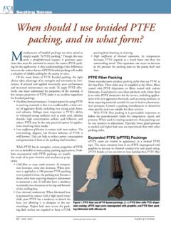
5 The intent of most mechanical sealsin submersibles is to protect bearing lubricant fromthe flow stream. Generally, these seals are single ordual liquid-lubricated designs. Dual liquid-lubricat-ed seals typically use a reservoir to provide cleanfluid to the inner and outer dual mechanical seals. JULY 2005 & SYSTEMS18 SEALING SENSEFrom the voice of the fluid SEALING industryPPrreessssuurree vveelloocciittyy eexxpprreessssiioonnJuly05 PUMPS&SYSp18-19 6/22/05 6:18 PM Page 18 Vertical Single Stage Pumpscirculate fluid or liftit to a processing area. They are generally used inlower-pressure, but higher-speed services sealed witha single or split mechanical seal. They usually pro-vide adequate liquid lubrication, but may require apiping plan to remove vapor from around the sealand keep entrained solids from clogging or damag-ing the single mechanical seal.
6 Vertical Multi-Stage Pumpsare used to pumphigh-vapor-pressure liquids through a typically are high-speed and are sealed with a single (but more often) dualtandem mechanical seal. Gas seals are sometimesused in these services. piping PlansSeal vendors have developed a series of pipingplans that extend the life of mechanical seals in ver-tical pump services. (See API and ASME publica-tions for details.) Selecting the correct plan is criti-cal to seal survival. Remember that entrained gasesin the flow stream will rise to the highest point inthe system because, in most cases, they are lighterthan the fluid being pumped. Since the sealingdevice is generally located at the highest point abovethe fluid being processed, entrained gases will accu-mulate around it.
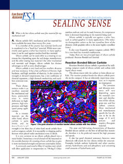
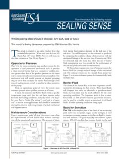
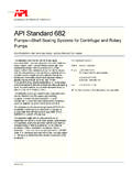
7 As previously discussed, thesegases provide poor face lubrication in high-speedand high-pressure service. Acting as an insulator,they also prevent frictional heat being conductedaway from the liquid lubricated seal faces. Toremove these gases, we use either API piping Plan13 or 14. Both plans specify that a tubing line (typ-ically 3/8 to 3/4 ) be connected from the glandport marked F (flush) to the pump suction orsump. This port allows the gases, which collectaround the inboard seal faces, to escape. piping Plan14 specifies an additional tubing line from a higher-pressure discharge point on the equipment to anadditional gland port marked "F" to provide a flowof liquid around the seal faces to remove heat.
8 API piping Plan 53 often is used in submersiblepump and mixer services to provide clean fluid tocool and lubricate both the inner and outer sealfaces of dual seals. It calls for a pressurized reservoirconnected to the seal gland via an input and outputtubing line to provide the clean fluid to the or a pumping device in the seal circu-lates the fluid to remove heat from the seal. API piping Plan 74 is used with gas seals. Itintroduces a small amount of clean gas to themechanical seal to establish a thin film between theseal faces. The gas then enters the product. The thinfilm minimizes or eliminates frictional heat andallows the gas seal to be used in low-, high- orextremely-high-speed Month: Comparing non-metallic expansionjoints with metallic in flue duct applicationsEditor s Note: We invite your questions on SEALING issues and will provide best-efforts answers based onFSA publications.
9 Please direct your questions to: & SYSTEMS JULY 2005 19 SEALING Senseis produced by the FSAto provide techni-cal information on SEALING systems and devices to pumpusers, contractors, distributors, OEMs and reps. TheMechanical Seal Divisionis one of six in the FSA with aspecific product focus. Among this division s morerecent contributions to the association s educationalmission is the Life Cycle Cost Estimator,a Web-basedsoftware tool for determination of pump seal LCC. Thefollowing members of the Mechanical Seal Divisionsponsor this SEALING SENSE :Advanced SEALING International (ASI) Chesterton Dow Elastomers LLCD aikin America, IncEagleBurgmann IndustriesFlex-A-Seal, Flow Solutions Div.
10 Seal GroupGarlock SEALING TechnologiesGreene Tweed & , Inc. Industrias Vago de Mexico SA de CVJohn CraneKC AmericaLatty International Multiples Industriales SAMetallized Carbon AM&TPPC Mechanical SealsSealing Equipment Products Co., Div. of Freudenberg-NOK AAPPII PPllaann 1144 -- SSuuccttiioonn aanndd DDiisscchhaarrggee RRee--CCiirrccuullaattiioonnJuly05 PUMPS&SYSp18-19 6/22/05 6:18 PM Page 19