Transcription of Searchpoint Optima Plus Infrared Point Gas Detector
1 Operating InstructionsSearchpoint Optima plus Infrared Point Gas DetectorMAN0551 Issue 07 - 09/082108M05012 Ensure that you read and understand these Operating Instructions BEFORE installing or operating any part of the Searchpoint Optima pay particular attention to the Safety For installations in the UK, the Code of Practice SELECTION, INSTALLATION AND MAINTENANCE OF ELECTRICAL APPARATUS FOR USE IN POTENTIALLY EXPLOSIVE ATMOSPHERES should be strictly observed. General recommendations are given in BS5345: Part 1: 1989. Specific requirements for flameproof (Type 'd'), intrinsically safe (Type 'i') and increased safety (Type 'e') protection are given in BS 5345: Part 3: 1979, BS 5345: Part 4: 1977 and BS5345: Part 6: 1978 respectively. For installations in North America, the National Electrical Code (NFPA 70 - 1990) or later issues should be strictly observed.
2 Elsewhere the appropriate local or national regulations should be The Code of Practice regarding SELECTION, INSTALLATION, USE AND MAINTENANCE OF APPARATUS FOR THE DETECTION AND MEASUREMENT OF COMBUSTIBLE GASES (OTHER THAN FOR MINING APPLICATIONS OR EXPLOSIVES PROCESSING AND MANUFACTURE) must be complied with. Refer to BS6959:1988 in the UK or the appropriate local or national Operators must be fully aware of the action to be taken if the gas concentration exceeds an alarm envIrOnmental SOlutIOnS3 MAN0551 Issue 07 - 09/082108M0501tOtal envIrOnmental SOlutIOnSCautIOnS1. Use only approved parts and accessories with the Searchpoint Optima To maintain safety standards, a planned maintenance programme is strongly recommended. This maintenance programme should take account of all operational conditions and requirements.
3 Maintenance and service operations should only be performed by personnel qualified to work upon Searchpoint Optima In order to maintain electrical safety, the unit must not be operated in atmospheres with more than 21% nOtICeS1. Honeywell Analytics Limited can take no responsibility for installation and/or use of its equipment if this is not done in accordance with the appropriate issue and/or amendment of the The user of this manual should ensure that it is appropriate in all details to the exact equipment to be installed and/or operated. If in doubt, the user should contact Honeywell Analytics Limited for If further details are required which do not appear in this manual, contact Honeywell Analytics Limited or one of their The Searchpoint Optima System is certified for and intended for use in potentially hazardous areas.
4 Install and use the Searchpoint Optima System in accordance with the latest Analytics Limited reserve the right to change or revise the information supplied in this document without notice and without obligation to notify any person or organisation of such revision or Issue 07 - 09/082108M05014 HelP uS tO HelP yOuEvery effort has been made to ensure the accuracy in the contents of our documents, however, Honeywell Analytics Limited can assume no responsibility for any errors or omissions in our documents or their Analytics Limited would greatly appreciate being informed of any errors or omissions that may be found in the contents of any of our documents and to this end we include the form opposite for you to photocopy, complete and return to us so that we may take the appropriate action.
5 MAN0551 Issue 07 - 09/082108M050156 MAN0551 Issue 07 - 09/082108M0501 COntentSSection Page1. INTRODUCTION 10 General 102. INSTALLATION VARIATIONS 14 ATEX Units 14 UL and CSA Units Only 153. INSTALLATION 17 Unpacking 17 Siting and Orientation 17 Installation Guide 18 Attachments and Options 22 General 22 Standard Weather Protection 22 Sunshade/Deluge Protection 22 Storm Baffle 23 Dust Barrier 23 Calibration Cap 24 Gassing Cover 24 Flow Housing 25 Remote Gassing Cell 26 Junction Box Adaptor Plate 27 European Duct Mounting Kit 28 US Duct Mounting Kit 31 MAN0551 Issue 07 - 09/082108M05017 Section Page4. ELECTRICAL CONNECTIONS 35 General 35 Analogue Connection 40 Digital Connection 40 +24V Power Connection 41 Earth Connection 415.
6 COMMISSIONING 46 General 46 Commissioning Procedure using SHC-1 and Multimeter 47 Electrical Commissioning and Tests 47 Gas Response Testing 48 System Level Testing 49 Final Commissioning 51 Commissioning Procedure with Multimeter Only 52 Electrical Commissioning and Tests (Multimeter) Only 52 Gas Response Testing (Multimeter) Only 54 System Level Testing 55 Final Commissioning (Multimeter) 56 Control System Setup 57 Functional Response Checking and Calibration 57 COntentS8 MAN0551 Issue 07 - 09/082108M0501 Section Page6. CALIBRATION 59 General 59 SHC-1 Hand-Held Interrogator 60 Connecting the Hand-Held Interrogator 61 Hand-Held Interrogator Operating Modes 62 Other Hand-Held Features 66 Calibrating the Controller 70 Calibrating the Sensor 737.
7 ROUTINE CHECKS 81 General 81 Inspection and Functional Response Check Procedure 81 Response Check Using Gassing Cover and %LEL Concentration Gas 83 Response Check Using Remote Gassing Cell & High %VV Gas 87 Inspection and Testing of Units Installed in Ducts 92 Removal and Refitting of Flow Housing 94 Removal of Flow Housing 94 Refitting of Flow Housing 94 COntentSMAN0551 Issue 07 - 09/082108M05019 Section Page8. FAULT FINDING 97 Troubleshooting 97 Diagnosis of Warning and Fault Messages 1039. REPLACEMENT OF HAND-HELD INTERROGATOR BATTERY 11110. ORDERING DETAILS 11311. SPECIFICATION 117 Searchpoint Optima plus Specification 117 Cross Interference to Other Gases and Vapours 124 Hand-Held Interrogator SHC-1 Specification 125 SHC Protection Device 126 Termination Unit DVC100 Specification 127 DX Termination Units Specification 12812.
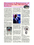
8 CERTIFICATION DETAILS 13013. WARRANTY 137 COntentS10 MAN0551 Issue 07 - 09/082108M05011. GeneralSearchpoint Optima plus is designed for use in potentially hazardous areas where it provides gas and vapour detection which is free from poisoning and independent of the presence of oxygen. The gas measuring parts of Searchpoint Optima plus are illustrated Optima plus uses the dual wavelength Infrared absorption principle to detect hydrocarbon gases and vapours in various concentration ranges. The instrument measures the number of molecules of the target gas in the light path, which depends on the concentration of the target gas. In addition to the relatively long and open measuring chamber, Searchpoint Optima plus can be fitted with a short enclosed flow through-cell as part of the chassis.
9 This is fitted with separate inlet and outlet ports and allows the application of high concentrations of gas for test BlockWindowHeater MirrorHeaterGas Measuring PathMAN0551 Issue 07 - 09/082108M050111 Searchpoint Optima plus is a micro-processor controlled, Infrared Gas Detector with comprehensive built-in self-diagnostic and fault finding facilities. An analogue 4 to 20mA output and digital communications are provided as standard. Full two way communication allows calibration and advanced self checking procedures to be used. To take advantage of these features a Hand-Held Interrogator unit may be connected to a Termination Unit or via the SHC Protection Device to other junction boxes. There are several different types of termination unit available:Termination UnitCertificationOutputDVC Type Termination UnitsDVC100 (I) MK2 ATEXI solated 4-20mADVC100 (M) MK2 ATEXI solated 4-20mA and MODBUSDX Type Termination UnitsDVC100 (I)ULIsolated 4-20mADX100 (M)ULIsolated 4-20mA and MODBUSS earchpoint Optima plus contains no moving parts and is available in a robust Stainless Steel explosion proof enclosure which has a M25 (ATEX) or 3/4 NPT (UL and CSA) mounting thread.
10 The unit operates over a wide temperature range and has a high degree of protection against dust and water ingress. It is designed to operate in the most arduous conditions and is supplied with a choice of weather protection Optima plus can be In-Duct Mounted, used in Sampling Systems, is easily confidence checked and may easily replace an existing sensor. Provided that existing cabling has three appropriately rated cores and the installation is correctly screened and earthed, it should not be necessary to replace the field cables or junction boxes. (A current to bridge converter may be required if the controller cannot be configured to accept 4-20mA signals).1. IntrODuCtIOn12 MAN0551 Issue 07 - 09/082108M05011. IntrODuCtIOnNo special tools are required for installation.