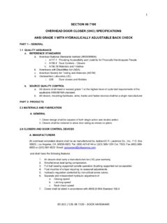
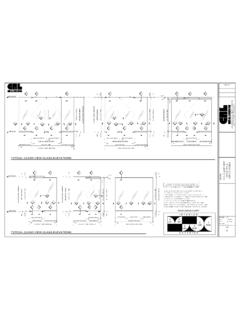
Transcription of SECTION 08 7100 COMMERCIAL DOOR HANDLES PART 1 - …
1 SECTION 08 7100 COMMERCIAL DOOR HANDLES Edit this document before use. Use this SECTION 08 7100 as a guide for preparing door hardware specifications and hardware schedules. Edit this SECTION for a specific project, and generate a hardware schedule listing hardware items required for each door opening. Additional hardware items need to be added and non-applicable items deleted. Throughout this SECTION , there is reference to other specification sections that might be contained in the project manual. PART 1 - GENERAL SECTION INCLUDES A. COMMERCIAL Door Pulls and HANDLES . B. Ladder Pulls C. Locking Ladder Pulls D. Center Lock Pull HANDLES RELATED REQUIREMENTS A. SECTION 08 1116 - Aluminum Framed Entrance doors B. SECTION 08 4210 - All Glass Entrances and Storefronts C. SECTION 08 4229 - Automatic Entrances; Other Than Balanced doors D.
2 SECTION 08 4236 - Balanced Door Entrances E. SECTION 08 8000 - Glass and Glazing Accessories REFERENCE STANDARDS A. American National Standards Institute (ANSI) 1. ANSI Architectural Door Trim 2. ANSI Auxiliary hardware 3. ANSI J405 Push/Pull/Kick Plates B. Architectural hardware Consultant (AHC) C. Builder hardware Manufacturers Association (BHMA) D. Door and hardware Institute (DHI) E. International Code Council (ICC) F. International Code Council/American National Standards Institute (ICC/ANSI) SUBMITTALS A. See SECTION 01 3000 Administrative Requirements, for submittal procedures. B. Product data for each hardware item, including function descriptions, materials, finishes, dimensions, power requirements for electrified items, and installation. C. Shop drawings illustrating special installation requirements and diagrams for wiring electrified items.
3 D. hardware Schedule: Complete itemization of each item of hardware to be provided for each door, cross-referenced to door identification numbers in Contract Documents. E. Keying: Provide schedule detailing final keying and indexing key sets to designated doors (If applicable). F. Manufacturer's instructions for preparing doors and frames to receive hardware and for hardware installation, adjustment, and maintenance. G. Warranty: Submit manufacturer warranty and ensure forms have been completed in Owner s name and registered with manufacturer. QUALITY ASSURANCE A. Installer qualifications: Engage an experienced installer who has completed installations of entrance doors and hardware similar in design and extent to those required for the project and whose work has resulted in construction with a record of success in service performance.
4 B. Manufacturer qualifications: Provide COMMERCIAL door hardware produced by a firm experienced in manufacturing COMMERCIAL door hardware that is similar to those indicated for this project and that have a record of success in service performance. C. Adjust hardware , and demonstrate that it functions properly. DELIVERY, STORAGE, AND HANDLING A. Ship door hardware to site in unopened boxes, clearly labeled with manufacturer's name and item description. B. Store and protect hardware until needed for installation. C. Inspect components for damage upon delivery. Unless minor defects in metal components can be made to meet the Architect s specifications and satisfaction, damaged parts should be removed and replaced. FIELD CONDITIONS A. Coordinate installation schedule with construction progress to avoid delay of the work and possible damage to the finished product.
5 WARRANTY A. See SECTION 01 7800 Closeout Submittals for additional warranty. PART 2 - PRODUCTS Part 2 - Products BASIS OF DESIGN (Architect to delete non-applicable items below) A. Ladder Pulls by Laurence Co. Inc., 1-800-421-6144 1. Straight or S Style 2. For 3/8 inch (10 mm) to 3/4 inch (19 mm) Thick Tempered Glass or 1-3/4 inch (44 mm) Aluminum or Wood doors . 3. Brushed or Polished Stainless Steel Finish 4. Standard Sizes: 24 inch (610 mm), 30 inch (762 mm), 36 inch (914 mm), 42 inch (1067 mm), 48 inch (1219 mm), 54 inch (1372 mm), 60 inch (1524 mm), 66 inch (1676 mm), 72 inch (1829 mm), 78 inch (1981 mm), or 84 inch (2134 mm). B. Locking Ladder Pulls by Laurence Co. Inc., 1-800-421-6144 1. Single or Double Locking 2. For 1/2 inch (12 mm) to 3/4 inch (19 mm) Thick Tempered Glass. 2. 1 inch (25 mm) or 1-1/4 inch (32 mm) Diameter Alloy 316 Brushed Stainless Steel 3.
6 1-1/4 inch (32 mm) Long Deadbolt Throw 4. Optional Black Leather Wrapped handle 5. Lock Operates at a minimum of 42 inches (1067 mm) Above Finished Floor. C. Glass Mounted Door HANDLES by Laurence Co. Inc., 1-800-421-6144 1. Back-to-Back or Single Sided Pull HANDLES . 2. Push and Pull HANDLES 3. Straight or Offset 4. For 3/8 inch (10 mm) to 3/4 inch (19 mm) Thick Tempered Glass. 5. Model #_____ (As Selected By Architect). 6. Finish a. Brushed Stainless b. Polished Stainless c. Satin Aluminum d. Dark Bronze Anodized e. Oil Rubbed Bronze f. Polished Brass D. Aluminum Door Mounted HANDLES by Laurence Co., Inc., 1-800-421-6144 1. Back-to-Back or Single Sided Pull HANDLES . 2. Push and Pull HANDLES 3. Straight or Offset 4. Model #_____ (As Selected By Architect). 5. Finish a. Brushed Stainless b. Polished Stainless c.
7 Satin Aluminum d. Dark Bronze Anodized e. Oil Rubbed Bronze f. Polished Brass E. Center locks for Glass doors by Laurence Co. Inc., 1-800-421-6144 1. 4 inch by 10 inch (102 by 254 mm), or 6 inch by 10 inch (152 by 254 mm), or Low Profile Model. 2. Deadlatch, or Long Throw Deadbolt, or Hook Throw Deadlock. 3. For 1/2 inch (12 mm) Tempered Glass 4. Optional Glass Keeper to Match Center Lock 5. Optional Electric Strike 6. Finish a. Brushed Stainless b. Polished Stainless c. Polished Brass d. Satin Anodized e. Black Bronze Anodized F. Substitutions: See SECTION 01 6000- Product Requirements. 1. For any product not identified as Basis of Design , submit information as specified for substitutions. GENERAL hardware SCHEDULE A. Hand of Door Refer to drawings for swing of each door leaf. Furnish hardware items suitable for indicated door movement.
8 B. Base Metals: Produce hardware units of basic metal and forming method indicated using the manufacturer's standard alloy, composition, temper, and hardness. C. hardware to conform to templates prepared for screw installation. D. Furnish installation screws with each hardware item. FINISH A. As shown on the drawings. B. To be selected by Architect from manufacturer s standard range. C. Touch-Up Materials: As recommended by coating manufacturer for field application. PART 3 - EXECUTION 3 - Execution INSTALLATION A. Prior to installation, verify that doors and frames are ready to receive hardware . Verify that hardware is free of surface defects, warping, and other defects that might affect the performance of hardware . B. Install hardware in accordance with manufacturer s instructions. ADJUSTING A. Adjust operating hardware to ensure proper operation.
9 CLEANING A. Remove protective material from pre-finished surfaces. B. Thoroughly clean, and polish in accordance with manufacturer's instructions. PROTECTION A. Protect installed products from damage during subsequent construction. END OF SECTION


