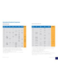
Transcription of Section 10: Basic and common symbols recognition
1 Section 10: Basic and common symbols recognition PURPOSE This Section aims to enable the student to extend their knowledge of Drawing Interpretation from engineering drawings produced to AS1100 standard. Objectives At the end of this Section you should be able to: o Interpret information on detail drawings of engineering components. Completion guidance Students should attempt this Section if the material relates to the engineering discipline they are employed or intend to be employed in. MEC076 engineering Drawing Interpretation 1 Resource Package December, 1998 I MEC076 - 10 -1 I h'" iI 'II 131 Basic and common symbols . recognition . The symbols covered in on the following pages are an example of the widespread use of symbols and abbreviations in industry. The symbols and abbreviations covered in this module relate to a few trades and professions.
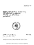
2 In some areas there are so many symbols and abbreviations that only someone who is heavily involved would know them all. If you do not know what a symbol means, do not guess, because in some industries it could lead to a serious injury or death if a wrong interpretation or decision is made. If you do not know what a symbol means, make sure you ask someone who definitely knows, not someone who does not like to admit that they do not know. You do not want the guess of someone else, you want someone who definitely knows or someone who has the latest publication containing the symbols . Radius Diameter Square Taper Slope MEC076 engineering Drawing Interpretation 1 Resource Package December, 1998 R D R8 R12 .015 .08 ~D65 -C-----} -8:-1:4 t::::". 1: ti " iii 'II 132 Feature identification Datum identification Equal First angle projection Third angle projection I A 135 1:- ; -:1 ~ [ MEC076 -10 -2 I Surface textures Surface texture Surface texture refers to the roughness of a surface.]
3 It can vary from very rough to very smooth, for example an aluminium casting may have the following surface textures: II rough cast II fine cast II die cast II rough machined II medium machined II fine machined Standard symbols V Basic symbol: used when surface finish can be produced by any convenient technique. ~ Modified symbol: finish done by a machining process. \! Modified symbol: indicating a surface finish without removal of material (for example, quality of an initial casting). Roughness value chart -:>'"3:_ >,:;< ' A""",",L \'//' 50 Rough oxy cut 25 Rough casting Rough machining Course machining Average machining Good machining Fine machining Fine grinding Honing Buffing Polishing Super polishing These numbers will become more relevant when the user is more conversant with the finishes they represent. Ask your teacher to supply samples of various finishes to a certain roughness value.
4 MEC076 engineering Drawing Interpretation 1 Resource Package December, 1998 Adding the roughness value to a standard symbol II .. fi " iii 'II 133 If a particular surface finish is required, but the production technique is not important, this symbol should be used: \y If a particular surface finish is required by using a machining operation, this symbol would be used: 7' When a surface finish is needed on a surface where no material can be removed, this ~ symbol would be used: V [ MEC076 -10 -3 [ Variations to standard symbols ~~/ V g:!/ V #8 ALL OVER EXCEPT WHERE OTHERWISE 51 .. 1ED Location of symbols on a drawing These symbols show maximum and minimum roughness values. Special surface characteristics are shown here. May be added to a drawing in a note form or inserted into the title block. This one is used when all the surfaces are to be machined to the same surface texture.]]
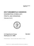
5 May be added to a drawing in a note form or inserted into the title block, when a single surface texture value applies to most surfaces. Exceptions should be indicated on the surfaces concerned. Indicates that an allowance of 3mm is to be provided for final machining. symbols may be located on an outline, projection line or leader line, provided that they can be 'Md from th, bototom 0' d,ht h""~ 7th' dca"'f-~_g. _____ ~ !------I. _. ~ Correct MEC076 engineering Drawing Interpretation 1 Resource Package December, 1998 -"\ ---_':':-_---6 ~"\ I. "\ Incorrect -hfUJ 134 A B c o E 2 3 DO NOT SCALE 20 60 _-t----+~M"-1'-"2 " I I ,," J o ID ~ !" ____ -J. _____ ,--------------; _ j I ----""'-l-----lfl-I-0 ~ ,-,--+-r-------+~--_ _W I I .016 R15 ;j; 2 .024 Vle:w on arrow B M20 x Y///////l~ Section A-A Olmen!Slons In mllllmetres Fillet radii R3 min Threads to AS 1275 SAMPLE DRAWING SHOWING SURFACE FINISH symbols 4 A B c o E MEC076 -10 -41 Basic symbols for Arc and Gas Welding Reference code 1.
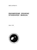
6 symbols for Welding No AS 26 2. Standards Association of Australia code for welding in building No AS 1554 Part 1 Butt welds General butt Square butt Single V butt Single bevel butt Single U butt Single J butt Full penetration butt weld by a welding procedure to be agreed MEC076 engineering Drawing Interpretation 1 Resource Package December, 1998 z \ c/; II \ h v v h "4:n 135 Flush Convex Concave MEC076 -10 -51 Structural Steel Profiles and Welding symbols The purpose of this page is to introduce you to some other symbols and abbreviations that are quite common on engineering drawings . Structural steel profiles are not drawn in most cases, nor are welds drawn or sketched as shown on the next page. These are only a few of the total number of symbol and abbreviations available in each area, and are produced here to make you aware of what area of engineering the symbols and abbreviations belong to.
7 Universal beam Universal column Universal bearing pile Channel Angle equal and unequal MEC076 engineering Drawing Interpretation 1 Resource Package December, 1998 D[I Depth greater than width. D[I Depth slightly greater than width. D[I Depth slightly less than width. D[[ --I B I--D:B:.t --IBI--200 UB 25 where UB 200 = D (nominal) 25 = mass in Kg/m 200 UC52 UC where 200 D (nominal) = 52 = mass in Kg/m 250 UBP 62 UBP where 250 = D(nominal) 62 = mass Kg/m 102 x 51 x 10 [ where [ 102 = D 51 = B 10 = mass Kg/m 127x 75 x10 L where L 127 = D 75 = B 10 = t fi lUI 136 150 x 150 x 5 SHS Square hollow SHS 150 x 75 x 5 RHS D[Gt Section or where or rectangular hollow ~ 150 = D RHS Section 75 = B 5 = t 75 ODx5 CHS Circular hollow dIG--t CHS where Section 75 = outside diameter 'd' 5 = t dL 20RD Round bar or rod RD where I 2 = d L 20SQ Square bar DIll SQ where JBL 20 = DorB Flat a)bar or a)FL 150 x 8 FL b)plate rll b)PL where (plate 900 to 3200 W or 150 = W in 100mm FL 8 = t increments)]]]]]]]]
8 1 MEC076 -10 -61 Sample of Welding symbols as They Would Appear on a Drawing MEC076 engineering Drawing Interpretation 1 Resource Package December, 1998 10 [7 10_ 1 MEC076 -10 -71 "1;1 j 137 Standard abbreviations A across flats addendum approximate arrangement assembly automatic auxiliary average B bearing bottom bracket brass building C capacity cast iron cast steel centre line centre-to-centre, centres chamfer channel cheese head chrome plated circle circular hollow Section circumference cold-rolled, steel computer-aided design and drafting computer-aided manufacture concentric counterbore MEC076 engineering Drawing Interpretation 1 Resource Package December, 1998 Refer to AS 1100 for the full I countersink CSK AF countersunk head CSKHD ADD cross-recess head C REC HD APPROX cup head CUPHD ARRGT cylinder CYL ASSY AUTO D AUX dedendum DED AVG detail DET diagonal DIAG diagram DIAG BRG diameter DIA BOT dimension DIM BRKT distance DIST BRS drawing DRW/DRG BLDG E elevation ELEV CAP external EXT CI CS F CL figure FIG CRS fillister head FILL HD CHAM flange FLG CHNL flat FL CH HD CP G CIRC galvanise GALV CHS galvanised iron GI CIRC galvanised iron-pipe GIP CRS general arrangement GA general-purpose outlet GPO CAD geometric reference frame GRF grade GR CAM grid GD CONC CBORE H modulus of inertia head HD mounting MIG height HT mushroom head MUSH HD hexagon HEX hexagon head HEX HD N hexagon-socket head HEX SOC HD negative NEG high strength HS nominal NOM high-tensile steel HTS nominal size NS horizontal HORIZ]
9 Not to scale NTS number NO inside diameter ID P internal INT parallel PAR part PT J pattern PATT jOint JT pipe P junction JUNC pipeline PL pitch-circle diameter PCD L phosphor bronze PH BRZ least material condition LMC plate pi left hand LH position POSN length LG positive POS longitudinal LONG prefabricated PREFAB pressure PRESS M pressure angle PA machine MACH or MIC malleable iron MI Q material MATL quantity QTY maximum MAX maximum material R condition MMC radius RAD mechanical MECH raised countersunk head RSDCSK HD mild steel MS rectangular RECT minimum MIN rectangular hollow Section RHS modification MOD reference REF modulus of elasticity E regardless of feature size RFS modulus of Section Z required REQD right hand RH 138 1 MEC076 -10 -81 k"~J Rockwell hardness A Rockwell hardness B Rockwell hardness C rolled-hollow Section rolled-steel angle rolled-sted channd rolled-steel jOist roughness value round round head S schedule Section sheet sketch spherical spigot spotface spring steel square square hollow Section stainless steel (corrosion resistance sted) standard Standards Association of Australia steel switch MEC076 engineering Drawing Interpretation 1 Resource Package December.
10 1998 HRA HRB HRC RHS RSA RSC RSJ Ra RD RDHD SCHED SECT SH SK Sf HER SPI SF SfRSIL sa SHS CRES SID SAA SI SW I tangent point temperature thread tolerance true position true profile U undercut universal beam universal column V vertical volume W wrought iron Y yidd point If IEMf IHD iOL If If UCUI UB UC VERI VOL WI Yf " it:o 139 [ MEC076 -10 - 9 [ Isometric and Oblique Dimensioning (not recommended for use in engineering ) 1. Projection lines are drawn:- Parallel to the plane Up or down for the length and width Out to the side for the height Away from the object. 2. Alternate extensions are drawn out to the left or to the right at 30 . 3. Dimensions may be placed on the view if they are clear. 4. Dimension figures are drawn parallel to the projection lines and face the reader. Wrong MEC076 engineering Drawing Interpretation 1 Resource Package December, 1998 Right , " it:o 140 Exercise 10-1 Exercise: Dimension the isometric drawing from the sizes shown on the orthogonal views.]]