Transcription of Section 16. Analog-to-Digital Converter (ADC)
1 16. Analog-to-Digital Converter (ADC). Section 16. Analog-to-Digital Converter (ADC). HIGHLIGHTS. This Section of the manual contains the following major topics: Introduction .. 16-2. Control Registers .. 16-6. Overview of Sample and Conversion Sequence .. 16-17. ADC Configuration .. 16-28. ADC Interrupt Generation .. 16-35. analog Input Selection for 16-37. Specifying Conversion Results Buffering for Devices with DMA and with ADC DMA Enable Bit (ADDMAEN) Set .. 16-52. ADC Configuration Example .. 16-56. ADC Configuration for Msps .. 16-57. Sample and Conversion Sequence Examples for Devices without DMA and for Devices with DMA but with ADC DMA Enable Bit (ADDMAEN) Clear .. 16-59. Sample and Conversion Sequence Examples for Devices with DMA and with ADDMAEN. Bit Set .. 16-71. Configuration Examples for Devices with Internal Op Amps.
2 16-81. Analog-to-Digital Sampling Requirements .. 16-84. Reading the ADC Result Buffer .. 16-85. Transfer Functions .. 16-87. ADC 16-89. Connection 16-89. Operation During Sleep and Idle 16-89. Effects of a 16-90. Design Tips .. 16-91. Related Application 16-92. Revision History .. 16-93. 2010-2013 Microchip Technology Inc. DS70621C-page 16-1. dsPIC33E/PIC24E Family Reference Manual Note: This family reference manual Section is meant to serve as a complement to device data sheets. Depending on the device variant, this manual Section may not apply to all dsPIC33E/PIC24E devices. Please consult the note at the beginning of the Analog-to-Digital Converter (ADC) chapter in the current device data sheet to check whether this document supports the device you are using. Device data sheets and family reference manual sections are available for download from the Microchip Worldwide Web site at: INTRODUCTION.
3 This document describes the features and associated operational modes of the Successive Approximation (SAR) Analog-to-Digital Converter (ADC) modules available on the dsPIC33E/PIC24E families of devices. This ADC module can be configured by the user application to function as a 10-bit, 4-channel ADC or a 12-bit, single channel ADC. On devices with Direct Memory Access (DMA), this ADC module can be configured to use DMA. or use a dedicated, 16-word memory mapped buffer instead of DMA. An ADC module block diagram for devices without op amps is provided in Figure 16-1. The ADC. module block diagram for devices with op am ps is provided in Figure 16-2. Note: Op amps are not available on all devices. Refer to the Op Amp/Comparator . chapter in the specific device data sheet for availability. The following key features are common to all dsPIC33E/PIC24E devices: SAR conversion Up to Msps conversion speed in 10-bit mode Up to 500 ksps conversion speed in 12-bit mode Up to 32 analog input pins External voltage reference input pins Four unipolar, differential Sample-and-Hold (S&H) amplifiers Simultaneous sampling of up to four analog input pins Automatic Channel Scanning mode Selectable conversion trigger source Up to 16-word conversion result buffer Operation during CPU Sleep and Idle modes Additional features are available on select dsPIC33E/PIC24E devices: Connections for up to three internal op amps (not available on all devices).
4 Connections to the Charge Time Measurement Unit (CTMU) and temperature measurement diode (not available on all devices). Channel selection and triggering can be controlled by the Peripheral Trigger Generator (PTG) (not available on all devices). Selectable Buffer Fill modes (not available on all devices). DMA support, including Peripheral Indirect Addressing (PIA) (not available on all devices). Note: Refer to the Analog-to-Digital Converter (ADC) chapter in the specific device data sheet to determine the availability of these additional features. Depending on the device variant, the ADC module may have up to 49 analog input pins, designated AN0-AN48, and four op amp outputs, designated OA1-OA3 and OA5. These analog inputs and op amp outputs are connected by multiplexers to four S&H amplifiers, designated CH0-CH3.
5 The analog input multiplexers have two sets of control bits, designated as MUXA (CHySA/CHyNA) and MUXB (CHySB/CHyNB). These control bits select a particular analog input for conversion. The MUXA and MUXB control bits can alternatively select the analog input for conversion. Unipolar differential conversions are possible on all channels using certain input pins. DS70621C-page 16-2 2010-2013 Microchip Technology Inc. Section 16. Analog-to-Digital Converter (ADC). 16. Channel Scanning mode can be enabled for the CH0 S&H amplifier. Any subset of the analog Analog-to-Digital Converter (ADC). inputs or op amp outputs (based on availability) can be selected by the user application. The selected inputs are converted in ascending order using CH0. The ADC module supports simultaneous sampling using multiple S&H channels to sample the inputs at the same time, and then performs the conversion for each channel sequentially.
6 By default, the multiple channels are sampled and converted sequentially. For devices with DMA and with the ADC DMA Enable bit (ADDMAEN) set, the ADC module is connected to a single-word result buffer. However, multiple conversion results can be stored in a DMA RAM buffer with no CPU overhead when DMA is used with the ADC module. Each conversion result is converted to one of four 16-bit output formats when it is read from the buffer. For devices without DMA, and for devices with DMA that have the ADC DMA Enable bit (ADDMAEN) clear, the ADC module is connected to a 16-word result buffer. The ADC result is available in four different numerical formats (see Figure 16-14). Note 1: A y' is used with MUXA and MUXB control bits to specify the S&H channel numbers (y = 0 or 123). Refer to Section Alternate Input Selection Mode for more details.
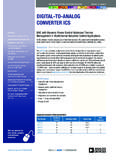
7 2: Depending on a particular device pinout, the ADC can have up to 49 analog input pins, designated AN0 through AN48, and four op amp outputs, designated OA1-OA3 and OA5. In addition, there are two analog input pins for external voltage reference connections (VREF+, VREF-). These analog inputs are shared with op amp inputs and outputs, comparator inputs, and external voltage references. When op amp/comparator functionality is enabled or an external voltage reference is used, the analog input that shares that pin is no longer available. The actual number of analog input pins and external voltage reference input configuration depends on the specific device. For more details, refer to the specific device data sheet. 2010-2013 Microchip Technology Inc. DS70621C-page 16-3. dsPIC33E/PIC24E Family Reference Manual Figure 16-1: ADC Block Diagram for dsPIC33E/PIC24E Devices without Op Amps AN0.
8 AN311. S&H0. Channel Scan +. CH0SA<4:0> CH0SB<4:0>(4) . CH0. CSCNA. AN1. VREFL. VREF+(1) AVDD VREF-(1) AVSS. CH0NA(4) CH0NB(4). AN0. AN3 S&H1. + VCFG<2:0>.. CH123SA CH123SB. CH1(2) AN6. AN9. ADC1 BUF0. VREFL. ADC1 BUF1(3). ADC1 BUF2(3). VREFH VREFL. CH123NA CH123NB. SAR ADC. AN1. AN5. S&H2. + ADC1 BUFE(3). ADC1 BUFF(3). CH123SA CH123SB. CH2(2) AN7. AN10. VREFL. CH123NA CH123NB. AN2. AN6. S&H3. +. CH123SA CH123SB . (2) AN8. CH3. AN11. VREFL. CH123NA CH123NB. ALTS Alternate Input (MUXA/MUXB). Selection Note 1: VREF+, VREF- inputs can be multiplexed with other analog inputs. For more details, refer to the specific device data sheet. 2: Channels 1, 2 and 3 are not applicable for the 12-bit mode of operation. 3: These buffers are unavailable if DMA is available and the ADDMAEN bit is set. 4: These bits can be updated with Step commands from the PTG module (not available on all devices).
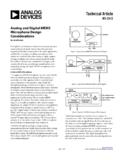
9 Refer to the Peripheral Trigger Generator (PTG) Module chapter in the specific device data sheet for availability. DS70621C-page 16-4 2010-2013 Microchip Technology Inc. Figure 16-2: ADC Module Block Diagram with Connection Options for ANx Pins and Op Amps 2010-2013 Microchip Technology Inc. This diagram depicts all of the available ADC connection options to the four S&H 00000. AN0-ANx Channel Scan 1. amplifiers, which are designated: CH0, CH1, CH2 and CH3. OA1-OA3, OA5 From CTMU CH0SA<5:0>(3) 0. CTMU TEMP Current Source (CTMUI). The ANx analog pins or op amp outputs are OPEN. connected to the CH0-CH3 amplifiers 11111 S&H0 CSCNA. through the multiplexers, controlled by the + A. CH0 CH0Sx SFR control bits, CH0Sx, CH0Nx, CH123Sx CH0SB<5:0>(3) B. CH0Sx . and CH123Nx. VREFL 0. CH0NA(3) A. 1. CH0Nx AN0/OA2 OUT/RA0 CH0NB(3) B.
10 000 CH0Nx Section 16. Analog-to-Digital Converter (ADC). 001. PGEC1/AN4/C1IN1+/RPI34/RB2 S&H1. ++. 010 + CH123SA<2:0> A. CMP1. 011 CH1 CH123Sx /OA1 . PGED1/AN5/C1IN1-/RP35/RB3 1xx CH123SB<2:0> B. OA1. PGEC3/VREF+/AN3/OA1 OUT/RPI33/CTED1/RB1 CH123x VREFL 0x CH123NA<1:0> A. 10 CH123Nx AN9/RPI27/RA11 11 CH123NB<1:0> B. 000 CH123Nx AN1/C2IN1+/RA1. 001 S&H2. + 010 + Alternate Input CH2 ALTS (MUXA/MUXB). 011. Selection 1xx OA2. CH123Sx VREF+(1) AVDD VREF-(1) AVSS. VREFL 0x 10. AN10/RPI28/RA12 11. PGED3/VREF-/AN2/C2IN1-/SS1/RPI32/CTED2/R B0 CH123Nx 000. 001 VCFG<2:0> ADC1 BUF0(4). AN8/C3IN1+/U1 RTS/BCLK1/RC2 + S&H3. + ADC1 BUF1(4). 010. 011. CH3 VREFH VREFL ADC1 BUF2(4). AN7/C3IN1-/C4IN1-/RC1 . OA3 1xx CH123Sx AN6/OA3 OUT/C4IN1+/OCFB/RC0. VREFL 0x SAR ADC. 10. AN11/C1IN2-/U1 CTS/RC11 11. DS70621C-page 16-5. OA5IN+/AN24/C5IN3-/C5IN1+/SDO1/RP20/T1CK /RA4 + CH123Nx ADC1 BUFE(4).