Transcription of Section 5: Drive Couplings - fptgroup.com
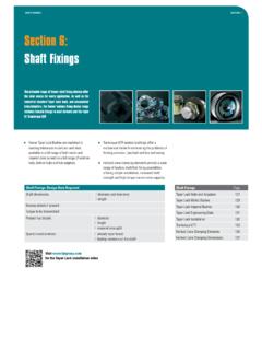
1 Fenaflex tyre Couplings from 24 to 14,675Nm, standard DBSE spacer variant, ATEX approved variant and flywheel version available. HRC, resilient Couplings from 30 to 3,150Nm, available in Taper Lock and pilot bore variants Jaw Couplings from to 280Nm with incidental misalignment capacity and quick fit spacer varaint. Rigid Taper Lock Couplings in 8 sizes up to 10,500 NmSection 5: Drive CouplingsSection : 5 Fenner shaft Couplings range from highly resilient to totally rigid and are all precision manufactured using high quality ferrous materials and the latest polymer coUPLinGSDrive Couplings : Design Data RequiredType of prime mover, or driving machineElectric motor starting arrangementEngine or compressor inertia of both machines (MR2 or GD2)
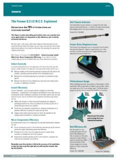
2 Rotational speed of prime moverPower rating of prime moverType of coupled machinePower absorbed by coupled machineHours/day duty & start/stop frequencyBoth coupled shaft diametersDistance between shaft endsLikely machine alignment quality > angular> parallel> axialVisit for the Drive Design AssistantDrive Couplings PageFenaflex Couplings 113 Fenaflex Power Ratings 114 Fenaflex Dimensions 115 Fenaflex Spacer Couplings 116 Fenaflex Flywheel Couplings 117 HRC Couplings 119 HRC Dimensions 120 Jaw Couplings 121 Rigid Couplings 123 Installation 124 Visit for online Fenaflex installation videosFenaflex Couplings112 Fenaflex CouplingsDRiVe coUPLinGSSection : 5 Fenner Advanced chain technologythe MARk oF enGineeRinG exceLLenceFenaflex Tyre CouplingsFlexible and EfficientLess Stress.
3 More Flexibility.> Simple time saving installation> Large misalignment capability, 4 angular, up to 6mm parallel and 8mm axial> internal load carrying cords are wound in both directions, so there is no problem reversing drives> tyres are available in standard and FRAS construction. Atex approved> Pump spacer and flywheel fixing variants Couplings - Power RatingsFen01/14 : Drive DeSiGn & MAintenAnce MAnUAL113 SeRVice FActoRSThe Fenaflex coupling is a highly flexible, torsionally elastic coupling offering versatility to designers and engineers with a choice of flange combinations to suit most coupling flanges are available in either F or H Taper Lock fitting or pilot bored, which can be finish bored to the required the addition of a spacer assembly the coupling can be used to accommodate standard distances between shaft ends, (DBSE)
4 Facilitating centrifugal pump Couplings can accommodate simultaneous maximum misalignment in all planes without imposing undue loads on adjacent bearings and the excellent shock-absorbing properties of the flexible tyre reduce vibration and torsional tyres are available in natural rubber compounds for use in ambient temperatures between 50OC and +50OC. Chloroprene rubber compounds are available for use in adverse operating conditions ( oil or grease contamination) and can be used in temperatures of 15OC to +70OC. The chloroprene compound should also be used when fire-resistance and anti-static (FRAS) properties are required, and it is this tyre material that is used with specific flange modifications in the ATEX approved (a) Service FactorDetermine the required Service Factor from table below.
5 (b) Design PowerMultiply the normal running power by the service factor. This gives the design power which is used as a basis for selecting the coupling .(c) coupling SizeRefer to Power Ratings table (page 114) and from the appropriate speed read across until a power greater than that required in step (b) is size of Fenaflex coupling required is given at the head of that column.(d) Bore SizeCheck from Dimensions table (page 115) that chosen flanges can accommodate required Fenaflex coupling is required to transmit 45kW from an electric motor which runs at 1440 rev/min to a rotary screen for 12 hours per day. The motor shaft is 60mm diameter and the screen shaft is 55mm diameter. Taper Lock is required.(a) Service Factor The appropriate service factor is (b) Design Power Design power = 45 x = of Driving UnitSPeciAL cASeSFor applications where substantial shock, vibration and torque fluctuations occur, and for reciprocating machines ( internal combustion engines, piston pumps and compressors) refer to your local Authorised Distributor with full machine details for motorsSteam turbinesinternal combustion engines Steam enginesWater turbineshours per day dutytype of Driven Machine10 and underover 10 to 16 16 10 andunderover 10to 16 16cLASS 1 Agitators, Brewing machinery, Centrifugal compressors andpumps.
6 Belt conveyors, Dynamometers, Lineshafts, Fans up to Blowers and exhausters (except positive displacement), 2*Clay working machinery, General machine tools, paper millbeaters and winders, Rotary pumps, Rubber extruders, Rotary screens, Textile machinery, Marine propellors and Fans over 3*Bucket elevators, Cooling tower fans, piston compressors and pumps, Foundry machinery, Metal presses, Paper mill calenders, Hammer mills, Presses and pulp grinders, Rubber calenders, Pulverisers and Positive displacement 4*Reciprocating conveyors, Gyratory crushers, Mills (ball, pebble and rod), Rubber machinery (Banbury mixers and mills) and Vibratory * It is recommended that keys (with top clearance if in Taper Lock bushes) are fitted on applications where load fluctuation is expected.
7 Couplings for use with internal combustion engines may require special consideration, refer to pages 117.(c) coupling SizeBy reading across from 1440 rev/min in the power ratings table the first power figure to exceed the required 63kW in step (b) is 75,4kW. The size of coupling is F90 Fenaflex.(d) Bore SizeBy referring to the dimensions table it can be seen that both shaft diameters fall within the bore range : 5 Drive coUPLinGSFenaflex CouplingsFenaflex Couplings - Dimensions114 Fenaflex Couplings - Power RatingsDRiVe coUPLinGSSection : 5 PoWeR RAtinGS (kW)Speedrev/mincouplings figures in heavier type are for standard motor speeds. All these power ratings are calculated at constant torque. For speeds below 100 rev/min and intermediate speeds use nominal torque chARActeRiSticS FLexiBLe tYReScharacteristicscoupling SizeF40F50F60F70F80F90F100F110F120F140F1 60F180F200F220F250 Maximum speed rev/min4,5004,5004,0003,6003,1003,0002,6 002,3002,0501,8001,6001,5001,3001,1001,0 00nominal torque nm tk n24661272503755006758751,3302,3253,7706, 2709,32511,60014,675 Maximum Torque Nm TK MAX641603184877591,0961,5172,1373,5475,6 429,33916,45523,50833,12542,740 Torsional Stiffness Nm/O513264163911261782964707781,3711,959 2,7603,562 Max.
8 Parallel misalignment end float mm mass. Torque Nm @ 10Hz TKW112653811271832523565919401,5562,7423 ,9185,5217,124 Resonance Factor V R777777777777777 Damping Coefficient tYRe coDe nUMBeRSUnless otherwise specified Fenaflex flexible tyres will be supplied in a natural rubber compound which is suitable for operation in temperatures 50OC to +50OC. A chloroprene compound is available which is Fire Resistant and Anti-Static (FRAS) and has greater resistance to heat and is suitable for operation in temperatures 15OC to +70OC. For temperatures outside these ranges consult your local Authorised FRAS tyre variant is used with specifically modified metal flanges to create the ATEX approved *Hexagonal socket caphead clamping screws on these torque figures should be regarded as short duration overload ratings for use in such circumstances as direct-on-line motor Fenaflex tyre Couplings have an angular misalignment capacity up to 4.
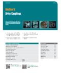
9 coupling SizeM Dimension (mm)Gap Between tyre ends (mm)clamping Screw torque (nm)Screw SizeF40*22215M6F50*25215M6F60*33215M6F70 23324M8F8025324M8F9027340M10F10027340M10 F11025340M10F12029350M12F14032555M12F160 30580M16F180466105M16F200456120M16F22055 6165M20F250596165M20 Fenaflex Spacer CouplingsFen01/14 : Drive DeSiGn & MAintenAnce MAnUAL115 DiMenSionS oF FenAFLex FLAnGeS tYPeS B, F & hFLAnGeScatalogue code SizetypeBush no. #Max Boretypes F & htype BScrew over keyAcDFG M Mass * (kg)inertia* (kgm )MetricinchLeJ Le033A0501F40B 32 " 10482 " 10482 38 " 13310079 " 13310079 45 " 165125103 " 165125103 50 " " 60 " " 70 " " 80 " " 90 " " 100 " " 130 " " 140 " " 150 " " 150 " " 160 " " 190 : 5 Drive coUPLinGSFenaflex Couplings - DimensionsDimensions in millimetres unless otherwise stated.
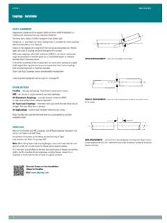
10 G is the amount by which clamping screws need to be withdrawn to release tyre. J is the wrench clearance to allow for tightening/loosening the bush on the shaft and the clamp ring screws on sizes F40. F50 and F60. The use of a shortened wrench will allow this dimension to be reduced. M is half the distance between flanges. Shaft ends, although normally located twice M apart, can project beyond the flanges as shown. In this event allow sufficient space between shaft ends for end float and misalignment.* Mass and inertia figures are for single flange with mid range bore and include clamping ring, screws and washers and half tyre. For pilot bore 'B' flange code as listed. Flanges are also available finish bored with keyway if required. Bore must be specified on order.