Transcription of Seismic Behavior of Beam Column Joints in Reinforced ...
1 Document No. :: Final Report :: A - Earthquake Codes IITK-GSDMA Project on Building Codes Seismic Behavior of Beam Column Joints in Reinforced Concrete Moment Resisting Frames by Deapartment of Civil Engineering Indian Institute of technology Madras Chennai Dr. Sudhir K Jain Department of Civil Engineering Indian Institute of Technology Kanpur Kanpur 1. Seismic DESIGN OF BEAM- Column Joints IN RC MOMENT. RESISTING FRAMES REVIEW OF CODES. a and Sudhir K. Jainb a Project Officer , Department of Civil Engineering, Indian Institute of Technology Madras, Chennai, India. b Professor, Department of Civil Engineering, Indian Institute of Technology Kanpur, Kanpur, India. Author to Correspond : Sudhir K Jain Email: Phone: 91-512-2597867. Fax: 91-512-2597866. Abstract The behaviour of Reinforced concrete moment resisting frame structures in recent earthquakes all over the world has highlighted the consequences of poor performance of beam Column Joints . Large amount of research carried out to understand the complex mechanisms and safe behaviour of beam Column Joints has gone into code recommendations.
2 This paper presents critical review of recommendations of well established codes regarding design and detailing aspects of beam Column Joints . The codes of practice considered are ACI 318M-02, NZS 3101: Part 1:1995 and the Eurocode 8 of EN 1998-1:2003. All three codes aim to satisfy the bond and shear requirements within the joint. It is observed that ACI 318M-02 requires smaller Column depth as compared to the other two codes based on the anchorage conditions. NZS 3101:1995 and EN. 1998-1:2003 consider the shear stress level to obtain the required stirrup reinforcement whereas ACI 318M-02 provides stirrup reinforcement to retain the axial load capacity of Column by confinement. Significant factors influencing the design of beam- Column Joints are identified and the effect of their variations on design parameters is compared. The variation in the requirements of shear reinforcement is substantial among the three codes. Submitted to a Journal for possible publication 2.
3 3. 1. Introduction Beam Column Joints in a Reinforced concrete moment resisting frame are crucial zones for transfer of loads effectively between the connecting elements ( beams and columns) in the structure. In normal design practice for gravity loads, the design check for Joints is not critical and hence not warranted. But, the failure of Reinforced concrete frames during many earthquakes has demonstrated heavy distress due to shear in the Joints that culminated in the collapse of the structure. Detailed studies of Joints for buildings in Seismic regions have been undertaken only in the past three to four decades. It is worth mentioning that the relevant research outcomes on beam Column Joints from different countries have led to conflicts in certain aspects of design. Coordinated programmes were conducted by researchers from various countries to identify these conflicting issues and resolve them (Park and Hopkins, 1989). Nevertheless, it is imperative and informative to bring out the critical aspects with respect to design of Seismic Joints adopted by various international codes of practice.
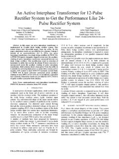
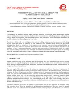
4 This paper presents a comprehensive review of the design and detailing requirements of interior and exterior Joints of special moment resisting Reinforced concrete frames, with reference to three codes of practices: American Concrete Institute (ACI 318M-02), New Zealand Standards (NZS 3101:1995) and Eurocode 8 (EN 1998-1:2003). The discussions with respect to Eurocode are pertaining to High' ductility class defined by that code. 2. Joints IN Reinforced CONCRETE MOMENT RESISTING FRAMES. Beam Column Joints are generally classified with respect to geometrical configuration and identified as interior, exterior and corner Joints as shown in This paper focuses to bring out the fundamental differences in the mechanisms of beam longitudinal bar anchorages and the shear requirements, two types of Joints such as interior joint and exterior joint are considered. With respect to the plane of loading, an interior beam- Column joint consists of two beams on either side 4.
5 Of the Column and an exterior beam- Column joint has a beam terminating on one face of the Column . (a) Interior Joint (b) Exterior Joint (c) Corner Joint Types of Joints in a Moment Resisting Frame 3. DESIGN APPROACH BY CODES. In Reinforced concrete moment resisting frame structures, the functional requirement of a joint, which is the zone of intersection of beams and columns, is to enable the adjoining members to develop and sustain their ultimate capacity. The demand on this finite size element is always severe and more complex due to the possible two-way actions in three-dimensional frame structures. However, the codes consider one direction of loading at a time and arrive at the design parameters for the joint. General Criteria The basic requirement of design is that the joint must be stronger than the adjoining hinging members, usually the beams or columns. It is important to see that the joint size is adequate early in the design phase, since otherwise the Column or beam size may need to be changed to satisfy the joint strength or anchorage requirements.
6 The design of beam Column Joints is predominantly focused on providing shear strength and adequate anchorage within the joint. The mechanisms involved in resisting the bond and shear for interior and exterior Joints have been discussed in detail by Paulay and Priestley, 1992. Judicious detailing of reinforcement is of paramount importance to obtain a ductile response of Reinforced concrete structures during a severe earthquake. One of the objectives of detailing is 5. to ensure that the full strength of reinforcing bars, serving either as principal flexural or transverse reinforcement, can be developed under the most adverse condition that an earthquake may impose. Detailing features relevant to beam- Column Joints are concerned with aspects such as transverse reinforcement for shear strength and confinement, spacing of Column longitudinal reinforcement and development length for embedded bars. In a global sense, the design procedure of beam- Column Joints consists of the following steps: Arrive at the preliminary size for members based on anchorage requirements for the chosen longitudinal bars.
7 Ensure adequate flexural strength of columns to get the desired beam yielding mechanism. Arrive at the design shear force for the joint by evaluating the flexural overstrength of the adjacent beams and corresponding internal forces. The simultaneous forces in the Column that maintain joint equilibrium must also be determined. From these, the joint shear force demand can be calculated. Obtain effective joint shear area from the adjoining member dimensions. Ensure that the induced shear stress is less than the allowable stress limit. The allowable shear stress limit is expressed as a function of the compressive strength or diagonal tensile strength of concrete. If not satisfied, alter the associated member dimensions, viz., width of the beam or depth of the Column . Provide transverse reinforcements both as confining reinforcement and as shear reinforcement. Provide sufficient anchorage for the reinforcement passing through or terminating in the joint.
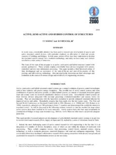
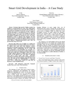
8 The above listed points are elaborated in sequence and discussed in detail with respect to code provisions. In this paper, the variables involved in the code provisions are expressed with the help of commonly adopted notations and symbols, for convenience, and may be different from the specific notations used by the three codes. Member Sizes In Seismic conditions involving reversed cyclic loading, anchorage requirements assume great importance in deciding the sizes of the members. This is because the limiting bond stress around the longitudinal bar is to be satisfied by the development length available within the member. 6. Depth of Member for Interior Joint In an interior joint, the force in a bar passing continuously through the joint changes from compression to tension. This causes push-pull effect with distribution of bond stress as shown in Fig. 2. The severe demand on bond strength necessitates that adequate development length for the bar be made available within the depth of the member.
9 In other words, for the longitudinal bar of the beam the development length should be provided by the Column depth and vice versa. In recognition of this, the codes limit the ratio between the bar diameter and the member depth. By adopting smaller diameter bars which require reduced development length, the sizes of the members can be controlled. Bond Stress Fig. 2 Bond Condition in an Interior Joint ACI 318M-02 suggests that where longitudinal beam reinforcement extends through an interior joint, the Column depth, hc shall not be less than 20 times the diameter of the largest longitudinal bar. hc db 20 (1). where db is the diameter of the longitudinal beam bar to be anchored and hc is the width of the Column parallel to the beam The purpose of the recommended value for hc/db is to provide reasonable control on the amount of potential slip of the beam longitudinal bars through the joint. However, bar slippage may occur even with Column depth of 20 db.
10 Slippage of bars considerably reduces the stiffness and energy dissipation capacity of the connection region. Therefore, longer development lengths 7. are desirable, particularly when combined with high shear stresses and low values of ratios of Column flexural strength to beam flexural strength (Leon, 1990). NZS 3101:1995 gives the following expression relating the bar diameter and the member depth. The expression explicitly involves the parameters that affect the bond performance such as axial load, condition of concreting done near the bar and material strengths. The code suggests an expression in the form of bar diameter to Column depth ratio as db t p f c . 6 f (2). hc s 0 f y where f c is characteristic cylinder strength of concrete; f y is characteristic yield strength of steel, f is , for one-way frame loading and for two-way frame loading; 0 is for overstrength for yield strength of steel at strain hardening; t is for a top beam bar where more than 300 mm of fresh concrete is cast below the bar and for all other cases and p is a factor to include beneficial effect of compression on Column where, N*.