Transcription of Seismic Bracing Systems
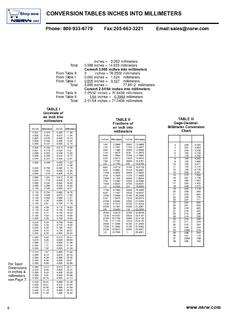
1 Seismic Bracing SystemsAs Approved by the California Officeof Statewide Health Planning andDevelopment for Metal FramingBracing ApplicationsSBS-3 Seismic MAP & conversion CHARTS Copyright 2002, Tyco Flow Control, All Rights ReservedCONVERSION OF UNIFIED UNITS OF MEASUREINTO METRIC EQUIVALENTSTo Convert FromIntoMultiply ByInches (In) (exactly)Feet (Ft)Centimeters (cm) (exactly)Square inches (In2)Square centimeters (cm2) (exactly)Cubic inches (In3)Cubic centimeters (cm3) (advp.)(Lb)Kilograms (kg).45359237 (exactly)Pounds per square inchKilograms per (kgf/mm2)Foot-pounds ( )Meter-kilograms (m-kg).138255 Pounds-force (Lbf)Kilonewton (kN).004448 Pounds-force (Lbf)Newton (N) OF CONTENTSG eneral Information .. 1-1 Design Procedures for Trapeze Hangers .. 2-1 Design Procedures for Single Pipe Hangers .. 2-5 Trapeze Bracing .. 3-1 Trapeze Fittings .. 3-3 Single Pipe Bracing .. 3-5 Horizontal Bracing .. 3-11 Vertical Bracing .. 3-13 Structure Attachments .. 4-1 Anchor Load Tables .. 5-1 Test Procedures for Anchors.
2 5-3 Typical Attachments .. 6-1 Concrete Inserts .. 6-2 Channel Styles .. 6-3 Channel Load Tables .. 6-6 Channel Nuts and Hardware .. 6-7 Channel Fittings .. 6-8 Design Examples .. 7-1 Date:Page35660 Clinton StreetWayne, Michigan 48184PH: (800) 521-7730 FAX: (734) 721-4106 William MerkelStructural EngineerRENEWEDF ixed Equipment AnchorageOffice of Statewide Health Planning and DevelopmentR-0120 February 1, 2002**Valid for 3 Years Maximum**Bill Staehlin(916) 324-9106 GENERAL INFORMATION1-11 These guidelines are intended to provide information for the Seismic restraint of nonstructural componentsin buildings based on the California Code of Regulations (CCR), Part 2, Title 24. Nonstructural componentsmay include hospital piping, electrical conduit, cable trays, and air handling Seismic horizontal force factor Zp = ZICpWp .Z=.4 for Seismic zone 4I= Weight of Component3. When supporting pressure piping, spacing of Seismic Bracing should not exceed two (2) times the verticalsupport spacing.
3 Stress in the pipes that are comparable to those required by ASME will The CCR, Part 2, Title 24, Table 23-P, Footnote 12 states the following: Seismic restraints may be omitted from the following installations:a. Gas piping less than one (1) inch inside Piping in boiler and mechanical equipment rooms less than inches inside All piping less than inches inside All piping suspended by individual hangers twelve (12) inches or less in length from the top of pipe tothe bottom of the support for the All electrical conduit less than inches inside rectangular air handling ducts less than six (6) square feet in cross-sectional area,g. All round air-handling ducts less than 28 inches in All ducts suspended by hangers 12 inches or less in length from the top of the duct to the bottom of thesupport for the nuts and bolts mounted to the Unistrut channels shall be tightened to the following minimumtorques:6. The charts and information presented on the following pages are intended as a guide only.
4 Prior toinstallation, the user and/or project engineer shall determine structural adequacy of supports and thesupporting structure and shall also determine compliance with applicable of this manual requires that layout drawings for the pipe/duct/conduit be used to determine bracelocations, sizes, anchorage and forces. These drawings are an integral part of the approval of the lateralforce Bracing system. The layout drawings shall be submitted to OSHPD as a deferred approval item priorto the installation of the lateral Bracing Diameter (In.)Bolt Torque ( )1 465 16113 819 Bolt Diameter (In.)Bolt Torque ( )1 2505 81003 4125 Date:Page35660 Clinton StreetWayne, Michigan 48184PH: (800) 521-7730 FAX: (734) 721-4106 William MerkelStructural EngineerRENEWEDF ixed Equipment AnchorageOffice of Statewide Health Planning and DevelopmentR-0120 February 1, 2002**Valid for 3 Years Maximum**Bill Staehlin(916) 324-9106 DESIGN PROCEDURES FOR TRAPEZE HANGERS2-11. Determine the support spacing using the smallest pipe diameter2.
5 Calculate the total weight of the pipes plus contents (W) on each trapeze using the following equation:W = S x (p1 + p2 + p3 + .. + pn)W = Total weight on trapeze (Ibs.)pn = Weight of pipe plus water ( )(page 2-1, table 1).S = Support spacing (ft) (page 2-1, table 1).3. Select clamps (pages 3-3, 3-4, tables 6 & 7). Either style, P1100 Series or P2558 Series can be pipe support spacing should be as per chart 1, row 3 page Select trapeze member using the total weight on the trapeze and the length of trapeze required to fit thegiven pipe sizes and quantities (page 3-1, 3-2, tables 2-5).5. Calculate horizontal Seismic force (Fh) assuming braces on alternate trapeze supports (page 2-2, figure 1).Select a brace assembly (page 3-11, details I-V) that has an Fh value that meets or exceeds the horizontalseismic necessary, Seismic force can be recalculated with braces on every trapeze (see figure 2).Pipe DataTable 1 Data for Schedule 40 Standard Weight PipeIncluding Horizontal Seismic Force of.
6 50 OfHorizontal SeismicPipeSectionSpacing PerPipe PlusForce/Ft. of PipeSizeModulusASME *Water(.5 x Pipe )InIn(S) Feet(P) 12** ** ** *ASME does not list all sizes shown, therefore some sizes have been proportioned between.**Spacing limited by CBC 1998. For gas pipe and copper pipe see CBC 1998 for support spacing. Date:Page35660 Clinton StreetWayne, Michigan 48184PH: (800) 521-7730 FAX: (734) 721-4106 William MerkelStructural EngineerRENEWEDF ixed Equipment AnchorageOffice of Statewide Health Planning and DevelopmentR-0120 February 1, 2002**Valid for 3 Years Maximum**Bill Staehlin(916) 324-9106 DESIGN PROCEDURES FOR TRAPEZE HANGERS2-2W = GRAVITY LOAD PER TRAPEZEFH = .5W x 2 = WROD TENSION MAX. = .5W+W = COMPRESSION MAX = .5 WFIGURE 1 BRACE ON ALTERNATE HANGERSNOTE: FOR LOAD REACTIONS SHOWN ON THISPAGE, THE PIPE OR CONDUIT LOADS ONTHE TRAPEZE SHOULD BE RELATIVELYUNIFORM AND SYMMETRICAL ALONG THELENGTH OF THE = GRAVITY LOAD PER TRAPEZEFH = .5 WROD TENSION MAX.
7 = .5W+.5W = COMPRESSION MAX = 0 FIGURE 2 BRACE ON EVERY HANGER Date:Page35660 Clinton StreetWayne, Michigan 48184PH: (800) 521-7730 FAX: (734) 721-4106 William MerkelStructural EngineerRENEWEDF ixed Equipment AnchorageOffice of Statewide Health Planning and DevelopmentR-0120 February 1, 2002**Valid for 3 Years Maximum**Bill Staehlin(916) 324-9106 DESIGN PROCEDURES FOR TRAPEZE HANGERS2-36. Check compression and tension in the rod. When diagonal braces are used to stabilize trapeze hangers,they will cause tension and compression forces to be added to the tension already in the rod (see figure 3).a. Select threaded rod that has a tension strength that meets or exceeds the required tension(page 3-14, table 10)Brace on alternate hangersTmax = (page 2-2, figure 1)Brace on every hangerTmax = (page 2-2, figure 2)b. Check compression in the selected threaded rod. When braces are used on every trapeze, no stiffeneris required. If the rod is subject to compression, it may require a stiffener.
8 Determine the percentage offull stress capacity on the rod using the following equation:Actual Compression Load Allowable Compression Load (page 3-13, table 9)Select clip spacing (L) based on percentage above (page 3-13, table 9).7. Determine if longitudinal braces are required using the following equation:Brace Spacing = Allowable Fh .25W(# of bays)Allowable Fh = Determined by assembly selected (page 3-11, details I-V)8. Check forces on pipe clamps using following equations:Vertical Force = Pipe Wt. per foot x Trapeze spacingTransverse Force = Pipe Wt. per foot x Lateral Brace Spacing x Force = Pipe Wt. per foot x Longitudinal Brace Spacing x pages 3-3 and 3-4 for allowable design forces. Revise spacing of braces if Check trapeze member for combined vertical and lateral Seismic loads using the following interactionequation: (Revise trapeze spacing or brace if necessary).10. Select concrete anchors if they are used (See pages 5-1 and 5-2), check tension and shear interactions asper ICBO reports.
9 []ActualVertical Force[]ActualHorizontal Force[]AllowableHorizontal Force[]+xx Force[]LateralReduction Factor[]LateralReduction Factor Date:Page35660 Clinton StreetWayne, Michigan 48184PH: (800) 521-7730 FAX: (734) 721-4106 William MerkelStructural EngineerRENEWEDF ixed Equipment AnchorageOffice of Statewide Health Planning and DevelopmentR-0120 February 1, 2002**Valid for 3 Years Maximum**Bill Staehlin(916) 324-9106 DESIGN PROCEDURES FOR TRAPEZE HANGERS2-4 MAX ROD TENSION = W 2 + W = ROD W 2 - W = 3 Date:Page35660 Clinton StreetWayne, Michigan 48184PH: (800) 521-7730 FAX: (734) 721-4106 William MerkelStructural EngineerRENEWEDF ixed Equipment AnchorageOffice of Statewide Health Planning and DevelopmentR-0120 February 1, 2002**Valid for 3 Years Maximum**Bill Staehlin(916) 324-9106 DESIGN PROCEDURES FOR SINGLE PIPE HANGERS2-51. Select hanger type (pages 3-6, through 3-10) given the diameter of the Determine the support spacing (page 2-1, table 1) and corresponding rod diameter(page 3-12, chart 1, row 2).
10 Calculate the total weight of the pipe and contents (page 3-12, chart 1, row 6) or use the following equation:W = S x pW = Total weight on hanger (Ibs.)p = Weight of pipe plus water ( )S = Support spacing (ft)3. Select a brace assembly (page 3-11, details I-V) with an allowable Fh greater than the applicable Fh(page 3-12, chart 1, row 7 or the following equation).Brace alternating HangersFh = .5Wx2 = WBrace every HangerFh = .5W4. Check maximum tension of rod (page 3-12, chart 1, row 8).5. Compression (see page 2-3, step 6b).6. Determine if longitudinal braces are required using the following equation:Brace Spacing = Allowable Fh (# of bays)Allowable Fh determined by assembly selected (page 3-11, details I-V) and clamp allowable force in thelongitudinal direction (page 3-7).7. Select concrete anchors if they are used (See pages 5-1 and 5-2), check tension and shear interactions asper ICBO reports. Date:Page35660 Clinton StreetWayne, Michigan 48184PH: (800) 521-7730 FAX: (734) 721-4106 William MerkelStructural EngineerRENEWEDF ixed Equipment AnchorageOffice of Statewide Health Planning and DevelopmentR-0120 February 1, 2002**Valid for 3 Years Maximum**Bill Staehlin(916) 324-9106 DESIGN PROCEDURES FOR SINGLE PIPE HANGERS2-6 FIGURE 4 LONGITUDINAL BRACETRANSVERSE BRACE Date:Page35660 Clinton StreetWayne, Michigan 48184PH: (800) 521-7730 FAX.