Transcription of SEISMIC DESIGN - Chapter 6 - Engineering
1 1 Chapter 6 SEISMIC DESIGN By Murat Saatcioglu1 Introduction SEISMIC DESIGN of reinforced concrete buildings is performed by determining earthquake DESIGN forces for the anticipated SEISMIC activity in the region, from the building code adopted by the local authority. The structural elements are then proportioned and detailed following the requirements of Chapter 21 of ACI 318-05. SEISMIC DESIGN forces are determined on the basis of earthquake risk levels associated with different regions. SEISMIC risk levels have been traditionally characterized as low, moderate and high.
2 These risk levels are considered in structural DESIGN to produce buildings with compatible SEISMIC performance levels. ACI 318-05 has three DESIGN and performance levels, identified as ordinary, intermediate and special, corresponding to low, moderate and high SEISMIC risk levels, respectively. Ordinary building DESIGN is attained for structures located in low SEISMIC regions without the need to follow the special SEISMIC DESIGN requirements of Chapter 21. These structures are expected to perform within the elastic range of deformations when subjected to SEISMIC excitations.
3 Buildings in moderate to high SEISMIC risk regions are often designed for earthquake forces that are less than those corresponding to elastic response at anticipated earthquake intensities. Lateral force resisting systems for these buildings may have to dissipate earthquake induced energy through significant inelasticity in their critical regions. These regions require special DESIGN and detailing techniques to sustain cycles of inelastic deformation reversals without a significant loss in strength. The latter can be ensured by following the SEISMIC provisions of ACI 318-05 outlined in Chapter 21.
4 The DESIGN and detailing requirements of ACI 31-05 are compatible with the level of energy dissipation assumed in selecting force modification factors and the resulting DESIGN force levels. While the level of detailing required may be intermediate for a building located in a moderate SEISMIC risk region, it may be at the special category (more stringent) for a building in a high SEISMIC risk region. This ensures appropriate level of toughness in the building. It is permissible, however, to DESIGN buildings for high toughness in the lower SEISMIC zones to take advantage of lower DESIGN forces.
5 1 Professor and University Research Chair, Dept. of Civil Engineering , University of Ottawa, Ottawa, CANADA 2 Structural members not designed as part of the lateral-force resisting system may have to be designed as gravity load carrying members . These members , if present in special moment-resisting frames or special structural wall systems located in high SEISMIC regions, must be protected during strong earthquakes as they continue carrying gravity loads tributary to them.
6 They are often referred to as gravity elements and they go for the ride during the earthquake motion. Chapter 21 provides DESIGN and detailing requirements for such members in Sec. Therefore, the structural engineer should first identify if the member under consideration for DESIGN is part of a lateral load resisting system, and if so, establish if the element is to be designed as intermediate or special SEISMIC resisting element. It is important to note that the requirements of Chapter 21 of ACI 318-05 are intended to be additional provisions, over and above those stated in other chapters of the Code for ordinary building DESIGN .
7 Limitations on Materials Certain limitations are imposed on materials used for SEISMIC resistant construction to ensure deformability of members within the inelastic range of deformations. The following are the limits placed on concrete and reinforcing steel used in earthquake resistant designs: i) f c 3000 psi ii) f c < 5000 psi for light-weight concrete, unless suitability is demonstrated by tests. iii) Reinforcement shall comply with ASTM A-706. ASTM A-615 Grades 40 and 60 are permitted if they satisfy items iv and v below.
8 Iv) (fy)Actual (fy)Specified 18,000 psi v) fu / fy vi) fyt 60,000 psi for all transverse reinforcement, including spirals. In addition to the above limitations, mechanical and welded splices of reinforcement and anchorage to concrete should meet the requirements of through Flexural members of Special Moment Frames Flexural DESIGN members designed to resist primarily flexure (Pu Agf c/10) are subject to additional DESIGN and detailing considerations for improved SEISMIC performance. These requirements consist of geometric constraints, minimum positive and negative moment capacities along member length, confinement of critical regions of elements for improved deformability, promotion of ductile flexural response and the prevention of premature shear failure.
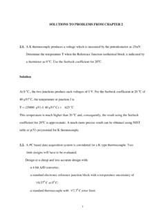
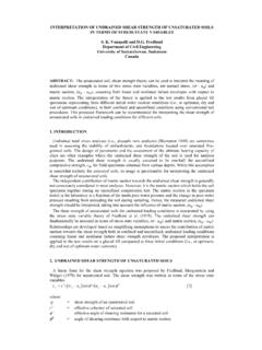
9 DESIGN aid SEISMIC 1 illustrates the geometric constraints, as well as minimum top and bottom reinforcement requirements for minimum moment capacity in each section during lateral load reversals. The same DESIGN aid also shows the spacing requirements for concrete confinement at potential plastic hinge locations at member ends (within a distance equal to 3twice the member depth). The transverse confinement reinforcement consists of hoops, which may be made up of two pieces as illustrated in SEISMIC 2.
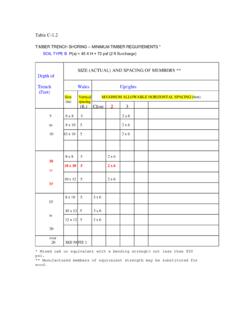
10 Where hoops are not required outside the plastic hinge region, stirrups with SEISMIC hoops should be used as also illustrated in SEISMIC 2. Shear DESIGN SEISMIC induced energy in special moment resisting frames is expected to be dissipated through flexural yielding of members . During inelastic response, however, the members should be protected against premature brittle shear failure. This is ensured by providing sufficient shear capacity to resist SEISMIC DESIGN shear forces. SEISMIC DESIGN shear Ve in plastic hinge regions is associated with maximum inelastic moments that can develop at the ends of members when the longitudinal tension reinforcement is in the strain hardening range (assumed to develop fy).