Transcription of Seismic Design of Earth Retaining Structures
1 Seismic Design of Earth Retaining Structures By Atop Lego, (Struct.) SSW (E/Z) AP, PWD; Itanagar Introduction The problem of Retaining soil is one the oldest in the geotechnical engineering; some of the earliest and most fundamental principles of soil mechanics were developed to allow rational Design of Retaining walls. Many approaches to soil retention have been developed and used successfully. In the recent years, the development of metallic, polymer, and geotextile reinforcement has also led to the development of many innovative types of mechanically stabilized Earth retention system.
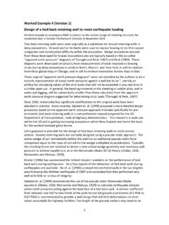
2 Retaining walls are often classified in terms of their relative mass, flexibility, and anchorage condition. The common types of the Retaining wall are: 1. Gravity Retaining wall 2. Cantilever Retaining wall 3. Counter fort Retaining wall 4. Reinforced Soil Retaining wall 5. Anchored bulkhead Fig. 1 Common type of Retaining Wall Gravity Retaining walls (Fig 1 a) are the oldest and simplest type of Retaining walls. The gravity wall Retaining walls are thick and stiff enough that they do not bend; their movement occurs essentially by rigid body translation and or by rotation. a. Gravity Wall b. Cantilever wall c.
3 Reinforced soil wall d. Anchored bulkhead e. Counterfort Retaining 2 The cantilever Retaining wall as shown in bends as well as translates and rotates. They rely on the flexural strength to resist lateral Earth pressures. The actual distribution of lateral Earth pressure on a cantilever wall is influenced by the relative stiffness and deformation both the wall and the soil. In the present context considering the maximum applicability of free standing gravity Retaining wall the presentation is focused mainly on the Seismic Design of gravity Retaining wall. (For details of other type the book Foundation Analysis and Design by Bowles;McGraw5 Hill International Edition, 1997 may be referred).
4 Type of Retaining Wall Failure To Design Retaining walls, it is necessary to know how wall can fail. Under static condition the Retaining walls are acted upon by the forces like; 1. body forces related to mass of the wall 2. by soil pressure 3. by external forces such as those forces transmitted by braces etc. A properly designed Retaining wall will achieve equilibrium of those forces including shear stresses that approach the shear strength of soil. During Earth quake, however the inertial forces and changes in the soil strength may violate the equilibrium and cause permanent deformation of the wall. Failure whether by sliding, tilting, bending or some other mechanism, occurs when these permanent deformations becomes excessive.
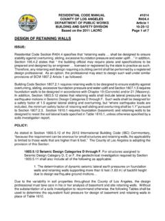
5 The types of failure of Retaining wall are as shown below in Typical failure mechanism of gravity wall Weak or liquefied a. Sliding failure b. Overturning Failure c. Gross instability failure 3 Gravity wall usually fail by rigid body mechanism such as sliding and/or overturning or by gross instability. Sliding occurs when horizontal force equilibrium is not maintained, that is when the lateral pressure on the back of the wall produces a thrust that exceeds the available sliding resistance of the base of wall. Overturning failure occurs, when moment equilibrium is not satisfied. In this situation bearing failure at the base are often involved.
6 In cantilever Retaining wall also, the similar type of failure occurs as that of in the gravity wall. In addition, the flexural failure mechanism also occurs in cantilever wall. Static Pressure on Retaining Wall The Seismic behavior of Retaining wall depends on the total lateral Earth pressure that develops during the Earth shaking. This total pressure includes both the static gravitational pressure that exist before earthquake occurs and the transient dynamic pressure induced by the earthquake. Therefore, the static pressure on the Retaining wall is of significant in the Seismic Design of Retaining wall and hence a brief review of static Earth pressure is presented.
7 Calculation of Static Earth Pressure: Rankine Theory Rankine (1857) developed the simplest procedure for computing the minimum active and maximum passive Earth pressure. For minimum active condition, Rankine expressed the pressure at a point on the back of a Retaining wall as avaaKcKp2/ = (1) Where Ka is the coefficient of minimum active Earth pressure, /v is the vertical effective stress at the point of interest, and c is the cohesive strength of the soil. When the principal stress planes are vertical and horizontal (as in case of a smooth vertical wall Retaining a horizontal backfill), the minimum active pressure coefficient is given by the equation: =+ =245tansin1sin12 aK (2) For the case of the cohesionless backfill inclined at angle with the horizontal infinite slope solution can be used to compute aK as.
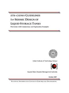
8 2222coscoscoscoscoscoscos + =aK (3) The pressure distributions on the back of the wall, as indicated by the equation (1), depend on the relative magnitude of the frictional and cohesive components of the backfill soil strength as given below in Fig 3. 4 )2/45(tan2 =aK /2czo= )2/45tan(2 + =czo zKpaa = czpp2 = )2/45tan(2)2/45(tan2 =czpa 2/2 HKPaa = 22222/ccHHPa+ = 2/2)2/45tan(2)2/45(tan2222ccHHPa+ = (a). (b). (c). Minimum Rankine active Earth pressure distribution for back fill with various combination of friction and cohesive strength; (a) Frictional resistance, no cohesion; (b) Cohesive soil, no frictional resistance; (c) combined cohesion and friction ( Cramer) Although the presence of cohesion indicates that tensile stresses will develop in between the upper portion of the wall backfill, tensile stresses do not actually develop in the field.
9 The creep, stress relaxation and low permeability characteristics of the cohesive soil render them undesirable as backfill materials for the Retaining Structures . Hence their use as filling materials should be avoided. The Rankine theory predicts triangular active pressure distribution oriented parallel to the backfill surface for homogeneous cohesionless backfill. The resultant active Earth pressure PA acts at a point located at height H/3 above the base of the wall height with the magnitude: 221 HKPaA = (4) Under maximum passive condition, Rankines theory predicts wall pressure given by the relation pvppKcKp21+= , , c=0 , =0, c , ,c zo Height of tension Failure surface Failure surface Failure surface 450+ /2 450 450+ /2 Pa Pa Pa z 5 where pKis the coefficient of maximum Earth pressure.
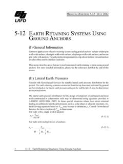
10 For smooth, vertical walls Retaining horizontal backfillspK is calculated from the relation; += +=245tansin1sin12 pK (5) and for backfill inclined at to horizontal 2222coscoscoscoscoscoscos +=pK (6) The passive pressure distribution for various backfill strength characteristics are shown in Fig 5. )2/45(tan2 +=pK zKppp = czpp2+= )2/45tan(2)2/45(tan2 + +=czpp 2/2 HKPa = cHHPa2212+= )2/45tan(2)2/45(tan222 +++ =cHHPp (a). (b). (c). Maximum Rankine passive Earth pressure distribution for back fill with various combination of friction and cohesive strength; (a) Frictional resistance, no cohesion; (b) Cohesive soil, no frictional resistance; (c) combined cohesion and friction ( Cramer) , , c=0 , =0, c , ,c Failure surface Failure surface Failure surface 450.