Transcription of Selection and Determination of Tubing …
1 CHAPTER. 3. Selection and Determination of Tubing and production Casing Sizes OUTLINE. Overview Solving Process Method of Selecting and Overview of Nodal Analysis Method of Analyzing Determining Maximum Selection and Tubing Size Sensitivity Tubing Size under Determination of Tubing and Affected by Inflow Condition of Meeting production Casing Sizes for Performance Carrying Liquid in Gas Flowing Wells Case 5 Well Importance of Sensitivity Solving Process Case 9. Analysis of Tubing Size production Casing Size Solving Process Sensitivity Analysis and Determination of Flowing Selection and optimization of Tubing Well Determination Method Size of Flowing Well Selection and of Minimum Tubing optimization Method Determination of Tubing and Size Avoiding Erosion Based on Surface production Casing Sizes for due to Excessive Flow Tubing Pressure Gas Wells Velocity in Gas Well Derived by Given Selection and Determination Case 10. Separator Pressure of Tubing Size of Natural Solving Process optimization Method Gas Well production Casing Size Based on the Given Selection and Determination of Natural Wellhead Tubing Determination Method Gas Well Pressure pwh of Tubing Size with Selection and Case 1 Minimum Energy Determination of Tubing and Solving Process Consumption of Lifting production Casing Sizes for Case 2 under Rational Artificial Lift Wells Solving Process production Rate Prediction of Daily Liquid Case 3 Case 6 production Rate Level in Solving Process Solving Process the High Water Cut Period Tubing Size optimization Case 7 Artificial Lift Mode Method of Ensuring Solving Process Determination Longer Flowing Period Case 8 Preliminary Selection of Case 4 Solving Process Artificial Lift Mode Advanced Well Completion Engineering, Third Edition Copyright # 2011, Elsevier Inc.
2 117. 118 CHAPTER 3 Selection and Determination of Tubing and production Casing Sizes production Mode Case 14 Selection and optimization Using the Solving Process Determination of Grade Weighted Selection and Determination production Casing Size Method of Tubing and production for Oil production Well Chart Method of Casing Sizes for Gas-Lift of Electric Submersible Selecting Oil Oil production Well Pump with Y-Shaped production Mode Case 15 Adapter Selection and Determination Solving Process Effects of Stimulation on of Tubing and production Selection and Determination Tubing and production Casing Sizes for Sucker of Tubing and production Casing Size Selection Rod Pump Well Casing Sizes for a Screw Selection and Case 11 Pump production Well Determination of Tubing and Solving Process Selection and Determination production Casing Sizes for Selection and Determination of production Casing Size Heavy Oil and High Pour- of Tubing and production for Dual-String production Point Oil production Wells Casing Sizes for Hydraulic Well Heavy Oil Recovery by Piston Pump Well Selection and Waterflooding Case 12 Determination of Flowing production Solving Process production Casing for Oil production by Selection and Determination Dual-String Gas Lift Pumping Unit and Deep of Tubing and production Well Well Pump Casing Sizes for Hydraulic Case 16 Heavy Oil Recovery by Jet Pump Well Solving Process Steam Injection Case 13 Selection and Huff and Puff Solving Process Determination of Heavy Oil Recovery by Selection and Determination production Casing Steam-Flooding of Tubing and production Size for Other Dual- High Pour-Point Crude Casing Sizes for Electric String production production Submersible Pump Well Well References OVERVIEW.
3 production rate of the oil well cannot be The Selection and Determination of Tubing and achieved at the high water cut stage. In order production casing sizes and the hole structure to change this traditional practice, this chapter design are the important links in the well com- will prove the rational Selection and determina- pletion process. The traditional practice is that tion of production casing size to the full extent. the hole structure is designed and the production In accordance with the reservoir energy and the casing size is determined by drilling engineering. requirements of production engineering, the After a well completion operation, the Tubing rational Tubing size should first be determined size and the mode of production are selected under a different production mode, and the and determined by production engineering on admissible minimum production casing size is the basis of the production casing that has been then selected and determined. At the flowing determined.
4 The result of this practice is that production stage, the rational Tubing size can the production operations are limited by the be selected and determined using the sensitivity production casing size, many oil and gas wells analysis of Tubing size, which is based on cannot adopt the adaptable technology and tech- the nodal analysis. At the artificial lift stage, nique, the stimulation is difficult to conduct, the rational Tubing size is closely related to the and the requirement of increasing the fluid requirement of stable oil production during oil CHAPTER 3 Selection and Determination of Tubing and production Casing Sizes 119. field development and the specific lifting mode. casing sizes by other special technological require- Therefore, the nodal analysis is briefly described ments; and max maximum value function. at first, and the Selection and Determination of For a heavy oil production well, the Tubing Tubing and production casing sizes are then and production casing sizes should be calculated described in detail.
5 As shown in Equation (3-3): The Tubing and production casing sizes of oil (3-3). and gas wells should be selected and determined Tubing and production casing sizes of heavy oil before well completion. The Tubing size can be production well max fTt1 , Tt2 , Tt3 g changed, but the production casing cannot be changed after well completion. Therefore, the where Tt1 Tubing and production casing sizes type of well, production mode, stimulation, oil by artificial lift selected; Tt2 Tubing and pro- properties, and requirements of production engi- duction casing sizes by heavy oil production ;. neering in the entire production process should Tt3 Tubing and production casing sizes by other be considered when a production casing size is special technological requirements; max maxi- selected and determined; that is, natural gas wells, mum value function. flowing wells, artificial lift wells, stimulation, and After the Tubing and production casing sizes heavy oil production have different requirements are determined, the casing program of a specific for selecting Tubing and production casing sizes.
6 Well is determined in accordance with well Thus, for a specific well, the aforementioned fac- depth, technical requirements of drilling technol- tors should be considered when the rational Tubing ogy, complexity of oil and gas reservoir, and and production casing sizes are determined. characteristics of overburden. For a natural gas well, both production opti- The slim hole (hole size 5 in.) completion mization and stimulation should be consid- mode includes open hole, slotted liner, and liner ered. Therefore, the Tubing and production cementing perforated completions. In addition, casing sizes should be computed as shown in the monobore well completion technique has Equation (3-1): been used by Shell. The slim hole completion is basically the same as the conventional wellbore (3-1) completion, except that the matching techniques Tubing and production casing sizes of natural of the slim hole, including perforating, stimula- gas well max fT1 , T2 , T3 g tion, artificial lift, downhole tools, and fishing where T1 Tubing and production casing sizes tools, should be considered in order to ensure by production optimization ; T2 Tubing and the normal production from a slim hole.
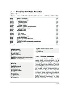
7 production casing sizes by stimulation; T3 . Tubing and production casing sizes by other spe- cial technological requirements; max maxi- OVERVIEW OF NODAL. mum value function. ANALYSIS. For a conventional oil production well, the The oil and gas flow from reservoir to surface Tubing and production casing sizes should be separator is shown in Figure 3-1. calculated as shown in Equation (3-2): The total fluid pressure loss from reservoir (3-2) deep to surface separator is composed of several Tubing and production casing sizes of conventional sections of pressure loss caused by resistance: oil production well max ft1 , t2 , t3 , t4 g pressure loss through porous media (first pres- where t1 Tubing and production casing sizes sure subsystem), pressure loss through well com- at flowing stage by production optimization ; pletion section (second pressure subsystem), t2 Tubing and production casing sizes by artifi- total pressure loss through Tubing string (third cial lift selected; t3 Tubing and production casing pressure subsystem), and total pressure loss sizes by stimulation; t4 Tubing and production through flowline (fourth pressure subsystem).
8 120 CHAPTER 3 Selection and Determination of Tubing and production Casing Sizes FIGURE 3-1 Various pressure losses in the production system. 1. Fluid pressure loss through porous media This pressure loss can be determined by In accordance with the relation between the calculation under the multiphase flow reservoir pressure, bottomhole flowing pres- condition in Tubing string. At present, there sure, oil saturation pressure, and the theory are various methods to calculate multiphase of mechanics of fluid through porous media, flow in pipe. the pressure distribution relations of single- 4. Total fluid pressure loss through flowline phase liquid flow, single-phase gas flow, The same calculation method as that of two-phase flow of oil and gas, three-phase multiphase flow in pipe is used. flow of oil, gas, and water, and dissolved gas drive and the oil and gas inflow perfor- The oil and gas production passes through the mance relationship can be derived; thus the four subsystems in the preceding list, which can total fluid pressure loss through porous be joined together into a unity by setting up media can be determined.
9 Nodes. If the analog calculation of each subsys- 2. Fluid pressure loss through well completion tem is conducted, the whole production system section can be mathematically simulated. The nodal The fluid pressure loss through well comple- analysis method uses just such an analogy calcu- tion section is closely related to the well com- lation process to analyze and optimize the pro- pletion mode and can be calculated by duction system of an oil and gas well. When a calculating the total skin factor S under a differ- specific problem is to be solved by using the ent completion mode. nodal analysis method, it is usual to take aim 3. Total fluid pressure loss through Tubing at some node (known as the solution node) in string the system. The production system of an oil CHAPTER 3 Selection and Determination of Tubing and production Casing Sizes 121. and gas well can be simplified into two large of predicting the future inflow-performance rela- parts (that is, inflow and outflow parts) by select- tionship (IPR) curve in order to optimize com- ing the solution node.
10 For instance, when the pletion parameters and Tubing size using the solution node is selected at pwf of the bottomhole nodal analysis method. This is what well com- of the oil well, the inflow part includes the two pletion engineering pays the most attention to. subsystems, that is, the fluid flow through porous For an oil and gas well that has been put into media and the fluid flow through completion sec- production , the nodal analysis method is helpful tion, while the outflow part includes the other for scientific production management. two subsystems, that is, the fluid flow through The theory and practice of nodal analysis have Tubing string and the fluid flow through surface been described in detail in the related literature. flowline. Thus, the following two major prob- lems can be solved. Selection AND. 1. Under the condition of constant parameter Determination OF Tubing . values of the outflow part, the completion AND production CASING. section can be optimized using the nodal sys- SIZES FOR FLOWING WELLS.