Transcription of Selective Coordination - Cooper Industries
1 94 2005 Cooper BussmannCircuit breaker CurvesThe following curve illustrates a typical thermal magnetic molded case circuitbreaker curve with an overload region and an instantaneous trip region (twoinstantaneous trip settings are shown). circuit breaker time-current characteristic curves are read similar to fuse curves. The horizontal axis represents the current, and the vertical axis represents the time at which thebreaker interrupts the using molded case circuit breakers of this type, there are four basiccurve considerations that must be understood.
2 These are:1. Overload Region2. Instantaneous Region3. Unlatching Time4. Interrupting Rating1. Overload Region:The opening of a molded case circuit breaker in theoverload region is generally accomplished by a thermal element, while a magnetic coil is generally used on power breakers. Electronic sensing breakers will utilize CTs. As can be seen, the overload region has a wide tolerance band, which means the breaker should open within that area for aparticular overload Instantaneous Region:The instantaneous trip ( ) setting indicates themultiple of the full load rating at which the circuit breaker will open as quicklyas possible.
3 The instantaneous region is represented in the following curveand is shown to be adjustable from 5x to 10x the breaker rating. When thebreaker coil senses an overcurrent in the instantaneous region, it releases thelatch which holds the contacts unlatching time is represented by the curve labeled average unlatchingtime for instantaneous tripping. After unlatching, the overcurrent is not halteduntil the breaker contacts are mechanically separated and the arc is extinguished. Consequently, the final overcurrent termination can vary over awide range of time, as is indicated by the wide band between the unlatchingtime curve and the maximum interrupting time instantaneous trip setting for larger molded case and power breakers canusually be adjusted by an external dial.
4 Two instantaneous trip settings for a400A breaker are shown. The instantaneous trip region, drawn with the solidline, represents an = 5x, or five times 400A = 2000A. At this setting, thecircuit breaker will trip instantaneously on currents of approximately 2000A ormore. The 25% band represents the area in which it is uncertain whetherthe overload trip or the instantaneous trip will operate to clear the dashed portion represents the same 400A breaker with an = 10x, or10 times 400A = 4000A. At this setting the overload trip will operate up toapproximately 4000 amps ( 10%).
5 Overcurrents greater than 4000A ( 10%)would be cleared by the instantaneous of a circuit breaker is typically set at its lowest setting when shippedfrom the Unlatching Times:As explained above, the unlatching time indicates thepoint at which the breaker senses an overcurrent in the instantaneous regionand releases the latch holding the contacts. However, the fault current continues to flow through the breaker and the circuit to the point of fault untilthe contacts can physically separate and extinguish the arc. Once the unlatching mechanism has sensed an overcurrent and unlatched, the circuitbreaker will open.
6 The final interruption of the current represented on thebreaker curve in the instantaneous region occurs after unlatching, but withinthe maximum interruption relatively long time between unlatching and the actual interruption of theovercurrent in the instantaneous region is the primary reason that moldedcase breakers are very difficult to coordinate. This is an inherent problemsince the breaking of current is accomplished by mechanical Interrupting Rating:The interrupting rating of a circuit breaker is a criticalfactor concerning protection and safety.
7 The interrupting rating of a circuitbreaker is the maximum fault current the breaker has been tested to interruptin accordance with testing laboratory standards. Fault currents in excess ofthe interrupting rating can result in destruction of the breaker and equipmentand possible injury to personnel. In other words, when the fault level exceedsthe circuit breaker interrupting rating, the circuit breaker is no longer a protective the example graph below, the interrupting rating at 480 volts is 30,000 interrupting ratings on circuit breakers vary according to breaker type andvoltage level.
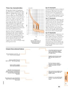
8 The marked interrupting on a circuit breaker is a three-pole ratingand NOT a single-pole rating (refer to pages 29 to 34 for more information).When drawing circuit breaker time-current curves, determine the proper interrupting rating from the manufacturer s literature and represent this interrupting rating on the drawing by a vertical line at the right end of the CoordinationCircuit BreakersCURRENT IN AMPERES100200300400600800100020003000400 06000800010,00020,00030,00040,00060,0008 0,000100, IN 480 VoltInstantanous RegionMinimumUnlatchingTimeOverload RegionMaximumInterrrupting Time400 Ampere circuit BreakerAdjustableInstantaneous TripSet at 5 = 5X( 25% Band)
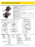
9 Adjustable MagneticInstantaneous TripSet at 10 = 10X( 10% Band)MaximumInterruptingTimeAverage UnlatchingTimes for Instantaneous TrippingAverage Unlatching TimesBreaker Tripping Magneticall yCurrent in Time in RMS AmpsSeconds5, , , , , RatingRMS Sym. Amps240V42,000480V30,000600V22,00095 2005 Cooper BussmannMedium to High Level Fault Currents circuit BreakersThe following curve illustrates a 400A circuit breaker ahead of a 90A fault above 1500A on the load side of the 90A breaker will open bothbreakers. The 90A breaker will generally unlatch before the 400A , before the 90A breaker can separate its contacts and clear the faultcurrent, the 400A breaker has unlatched and also will a 4000A short circuit exists on the load side of the 90A circuit sequence of events would be as follows:1.
10 The 90A breaker will unlatch (Point A) and free the breaker mechanism to startthe actual opening The 400A breaker will unlatch (Point B) and it, too, would begin the openingprocess. Once a breaker unlatches, it will open. At the unlatching point, theprocess is At Point C, the 90A breaker will have completely interrupted the fault At Point D, the 400A breaker also will have completely opened the , this is a non-selectivesystem, causing a complete blackout tothe other loads protected by the 400A printed by one circuit breaker manufacturer, One should not overlook thefact that when a high fault current occurs on a circuit having several circuitbreakers in series, the instantaneous trip on all breakers may.