Transcription of Series 200 Butterfly yValves
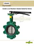
1 Series 200 Butterfly Butterfly Valves For over 40 years, Center Line has manufactured resilient Quality is designed into the Series 200 Butterfly valve, seated Butterfly valves. Today, Center Line continues to utilizing the phenolic-backed cartridge seat pioneered by manufacture these Butterfly valves as its primary product. Center Line. These valves feature precision-machined parts Industries using Center Line resilient seat valve products insuring years of dependable operation. With many body/. include: trim combinations, there is a Series 200 valve to meet your HVAC application. Chemical/Petrochemical Processing Food and Beverage Industry Power and Utilities Pulp and Paper Industry Stem Configuration: Gives positive attachment for handles or actuators. (Double D , 2" - 24"). Shaft Weather Seal: Actuator Flange: (Below bushing on some models). Accommodates all types of actuators; handles, gear operators, electric actuators, One-Piece Thru Shaft: and pneumatic actuators.
2 Ensures dependability (2" - 24" per ISO 5211). and positive disc positioning. Bushings: Stem bushing reduces torque and isolates the stem from the O-Ring: valve body, preventing seizure of Provides further the stem due to corrosion in the prevention of stem leakage stem journal. (4 Bushings) Seat Face: Negates need Smooth Finished Disc Flats: for flange gaskets. These mate with seat flats to give a highly efficient seal; Precision Taper Pin: prevents leakage into Ensure positive, shaft areas. vibration proof, shaft to disc connection. Field Precision Profile Disc: replaceable. Provides bubble-tight shut-off and assures minimum torque and longer seat life. Phenolic Backed Seat: Non-collapsible, stretch Supported Shaft Seal: resistant, blow out proof, Bonding of elastomer to field replaceable. phenolic backing ring protects against distortion, a common cause of shaft leakage. Representative Cutaway . A Crane Co. Company 2. Butterfly Butterfl Series y Valves 250 ButterflySeries Valves200.
3 * Series 200 Butterfly Valves Available in sizes 2" to 48". Available with handles (2" to 12"), manual gear operators Available in Wafer or Lug style body (2" to 30"). (2" to 48"), and electric or pneumatic actuators (2" to 48"). Full flange style body for 36" to 48" valves. Refer to Crane actuator bulletins for details of pneumatic and Wafer body features four alignment holes. electric actuators. Pressure ratings for tight shut-off at temperatures up to Designed to comply with MSS SP-67. the maximum limit of the seat material: Compatible with ANSI 125/150 flanges. 2" to 12" 200 psi, 125 psi for PTFE seat. Valves 2" to 20" meet the intent and have passed the AWWA. 14" to 48" 150 PSI. C-504-87 Section 5 proof of design tests. Ideal for on-off or throttling services. Type approval certification from ABS for marine applications (2" to 14"). Bi-directional dead-end capability to 200 psi (2" to 12"). and 150 psi (14" to 24") is available.
4 (*Note: Series 200 formally known as A & LT ). Operators mounted perpendicular to pipe. Valve Seating Torques (In-Lbs.). Standard Disc Differential Pressure Undercut Diff. Press. Valve 50 PSI P 100 PSI P 150 PSI P 200 PSI P 75 PSI P. Size Bushing Bushing Bushing Bushing Bushing Bronze PTFE Bronze PTFE Bronze PTFE Bronze PTFE Bronze PTFE. 2" 106 100 117 106 129 111 140 117 - - 2 1/2" 152 150 166 163 181 176 195 189 - - 3" 213 207 230 220 248 232 265 244 - - 4" 321 290 386 323 450 357 515 390 - - 5" 481 423 598 481 715 540 832 598 - - 6" 692 599 878 691 1,063 783 1,248 875 - - 8" 1,326 1,060 1,716 1,183 2,106 1,307 2,496 1,430 1,124 819. 10" 2,239 1,671 3,010 1,872 3,780 2,074 4,550 2,275 1,363 909. 12" 3,959 2,568 4,953 2,795 5,948 3,023 6,942 3,250 2,457 1,445. 14" 4,881 2,640 6,226 3,070 7,570 3,500 - - 4,400 2,300. 16" 7,020 4,260 8,580 4,880 10,140 5,500 - - 5,900 3,600. 18" 10,105 6,287 12,202 7,243 14,300 8,200 - - 8,300 5,500.
5 20" 13,923 8,360 16,582 9,180 19,240 10,000 - - 11,100 6,700. 24" 23,617 15,427 26,953 16,813 30,290 18,200 - - 17,300 12,100. 30" 39,721 27,313 43,391 29,407 47,060 31,500 - - 27,300 21,100. All torques shown on the chart were derived from test data using water at 60 F. For torques using dry gases, multiply these numbers by For torques involving other media, please consult the factory. There is no safety factor included in the numbers shown on this chart. For actuator sizing, Center Line recommends that these values be multiplied by for single valve applications, and for 3-way ("tee") applications. Under certain conditions, hydrodynamic torque can meet or exceed seating and unseating torques. When designing valve systems, hydrodynamic torque must be considered to help insure correct selection for the application. 3 A Crane Co. Company Series 200 Butterfly Butterfly Valves Seat Temperature Ratings Material Temperature Ratings F. Buna-N +10 to 180.
6 Abrasive Resistant +10 to 180. Buna-N. Neoprene +20 to 200. EPDM (2"- 16") -30 to 275. EPDM (18" & Above) -30 to 225. EPDM, Food Grade -30 to 225. (2" - 12"). Hypalon 0 to 275. Viton +10 to 275. High Temp. Viton * +10 to 400. PTFE over Buna-N. (125 psi, 2" - 12") +40 to 250. PTFE over Buna-N. (75 psi, 2" -12") +40 to 275. Although elastomers have an effective operating temperature range, when used in valves, these ranges may have to be modified. The temperature ranges shown in the table have been adjusted accordingly. For Low Temperature: While the seat materials selected for use in Center Line Butterfly valves are capable of withstanding lower temperatures without damage, the durometer of the elastomer is changed. This "hardening" of the seat may increase the operating torque beyond the structural limits of the stem and/or the disc to stem configuration. For High Temperature: When using High Temperature Viton , the operating pressure of the valve is reduced above 275 F.
7 CV Values Valve Sizing Coefficients (US-GPM @ 1 P). Size 10 20 30 40 50 60 70 80 90 . 2" 3 7 15 27 44 70 105 115. 2 1/2" 6 12 25 45 75 119 178 196. 3" 9 18 39 70 116 183 275 302. 4" 17 36 78 139 230 364 546 600. 5" 29 61 133 237 392 620 930 1022. 6" 45 95 205 366 605 958 1437 1579. 8" 2 89 188 408 727 1202 1903 2854 3136. 10" 3 151 320 694 1237 2047 3240 4859 5340. 12" 4 234 495 1072 1911 3162 5005 7507 8250. 14" 6 338 715 1549 2761 4568 7230 10844 11917. 16" 8 464 983 2130 3797 6282 9942 14913 16388. 18" 11 615 1302 2822 5028 8320 13168 19752 21705. 20" 14 791 1647 3628 6465 10698 16931 25396 27908. 24" 22 1222 2587 5605 9989 16528 26157 39236 43116. 30" 37 2080 4406 9546 17010 28147 44545 66818 73426. A Crane Co. Company 4. Butterfly Butterfl Series y Valves 250 ButterflySeries Valves200. H C J Sq. C J Dia. "F" Dia. "F" Dia. 4 Holes Eq. Sp. 4 Holes Eq. Sp. P on "G" Dia. BC 0n "G" Dia. BC. From 2" to 24" Valves For 30" Valve E Dia.
8 E Dia. E Dia. For 2"-24" Valves C. L of valve P P P. D D D. A A A. O. L of pipe C. N N. B B B. DISC K Bolt Circle K Bolt Circle K Bolt Circle BODY L 2 Dia. L 2 Dia. L1 Dia. M 2 No. of Holes M1 No. of Holes M No. of Holes Dimensions 2" - 30". Inches /. mm A B C D E F G H J K L1* L2* M1* M2* N O P. 2" 6 /8. 3. 3 /4. 1. 1 /4. 3. 1 /4. 1. /2. 1 3. /8 2 4. 3. 4 4. 3 5. 8-11 16. 11. 4 4 4. No. 3. 50 70 10 Wooduff #3. 2 1/2" 6 7/8 3 3/4 1 7/8 1 1/4 1. /2 3. /8 2 3 4 5 1 2 5. 8-11 16. 11. 4 4 4 3 4 No. 3. 65 70 10 Wooduff #3. 3" 7 1/8 4 1 7/8 1 1/4 1. /2 3. /8 2 3 4 6 5. 8-11 16. 11. 4 4 5 1 8 No. 3. 75 70 10 Wooduff #3. 4" 7 7/8 4 7/8 2 1/8 1 1/4 5/. 8. 3/. 8 2 3 4 7 1 2 5 -11. 8 16. 11 8 4 6 3 4 No. 9. 100 70 12 Wooduff #9. 5" 8 3/8 5 3/8 2 1/4 13/. 16. 3/. 4. 3/. 8 2 3 4 8 1 2 3 -10. 4 16. 13 8 4 7 3 4 No. 9. 125 70 14 Wooduff #9. 6" 8 7/8 5 7/8 2 1/4 1 1/4 3/. 4. 3/. 8 2 3 4 9 1 2 3 -10. 4 16. 13 8 4 8 5 8 No. 9. 150 70 14 Wooduff #9. 8" 10 1/4 7 1/8 2 1/2 1 3/4 7/.
9 8. 7/. 16 3 3 4 11 3 4 3 -10. 4 16. 13 8 4 10 9 16 No. 9. 200 102 17 Wooduff #9. 10" 11 1/2 8 1/4 2 3/4 1 3/4 1 1/8 7/. 16 3 3 4 14 1 4 7 -9. 8 16. 15 12 4 13 1 16 No. 15. 250 102 22 Wooduff #15. 12" 13 1/4 9 3/4 3 1/8 1 3/4 1 1/4 7/. 16 3 3 4 17 7 -9. 8 16. 15 12 4 16 1 8 No. 15. 300 102 24 Wooduff #15. 14" 14 1/2 11 3 1/8 1 3/4 1 1/4 7/. 16 3 3 4 18 3 4 1-8 11 16 12 4 17 1 8 No. 15. 350 102 24 Wooduff #15. 16" 15 3/4 12 3 1/2 2 1 5/16 7/. 8 6 1 2 21 1 4 1-8 11 16 16 4 20 5 " Sq. x 13/ ". 16 4. 400 165 27 18" 16 5/8 14 3/8 4 1/4 2 1 1/2 7/. 8 6 1 2 22 3 4 11/8 - 7 11 4 16 4 21 3 8 3 8" Sq. x 11 2". 450 165 27 . 20" 18 7/8 14 5/8 5 1/4 2 1/2 1 5/8 7/. 8 6 1 2 25 11/8 - 7 11 4 20 4 23 5 16 3 " Sq. x 13 ". 8 4. 500 165 32 24" 22 1/8 18 6 1/8 2 3/4 2 7/. 8 6 1 2 29 1 2 11/4 - 7 11 4 20 4 27 7 8 1 2" Sq. x 21 4". 600 165 36 30" 25 1/2 241/4 63/4 31/4 21/2 7/. 8 81/2 N/A 111/4 36 11/4 - 7 11/4 - 7 28 4 343/8 5 8" Sq. x 25 8". 750 *L1 and *M1 refer to Lug style valves, L2 and M2 refer to Wafer Style.
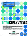
10 C dimension is listed with elastomer in the relaxed condition. Approximately 1/8" total compression is required for proper sealing with pipe flanges. Valves are designed for installation between ANSI Class 125 (Iron) and Class 150 (Steel) flanges. Gaskets are not needed, and should not be used since the seat face seals against the mating flange. If the valve is to be installed in plastic or fiberglass flanges, flange rings, or Van Stone style flanges, consult your Center Line agent or the factory for additional information. Center Line recommends that a blind flange be used on end of line applications. 1. Consult factory for dimension to 2 1/2" and 5" PTFE seated valves. O dimension is the valve clearance dimension. 5 A Crane Co. Company Series 200 Butterfly Butterfly Valves 6. 4. 7. 8. 9. 7. 3. 5*. 2. 10. 1. Sizes 2" 30". *Qty 0f 3 pins required for sizes 30" and above Bill of Materials 2" - 30". Item Description Materials Optional Materials 1 Body Cast Iron Ductile Iron 2 Disc Ductile Iron1 Aluminum Bronze, 316 SS, Monel 3 Seat Buna-N or EPDM Neoprene, Hypalon, Viton, PTFE, FDA, Abrasion Resistant 4 Shaft 416 Stainless Steel 316 Stainless Steel, Monel 5 Taper Pin 316 Stainless Steel Monel 6 Key Carbon Steel No Option Available 7 O-Ring Buna-N No Option Available 8 Bushing PTFE Luberized Bronze 9 Bushing PTFE Luberized Bronze 10 Bushing PTFE Luberized Bronze 1.