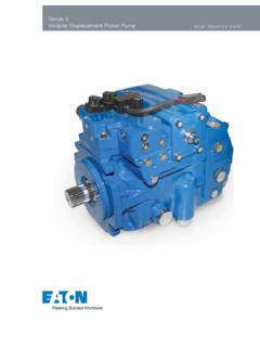
Transcription of Series 40 Axial Piston Pumps Technical Information
1 Series 40 Axial PistonPumpsTechnicalInformation520L0635 Rev E-2 June 20062 Series 40 Axial Piston PumpsTechnical Information 2005 Sauer-Danfoss. All rights reserved. Printed in accepts no responsibility for possible errors in catalogs, brochures and other printed material. Sauer-Danfoss reserves the right to alter its products without prior notice. This also applies to products already ordered provided that such alterations aren t in conflict with agreed specifications. All trademarks in this material are properties of their respective owners. Sauer-Danfoss and the Sauer-Danfoss logotype are trademarks of the Sauer-Danfoss Group. Front cover illustrations: F101 220, F101 221, F101 222, F101 223, P100 651 EOrganizatiOn and headingsTo help you quickly find Information in this manual, the material is divided into sections, topics, subtopics, and details, with descriptive headings set in red type. Section titles appear at the top of every page in large red type. Topic headings appear in the left hand column in BOLd red CaPitaL Letters.
2 Subtopic headings appear in the body text in bold red type and detail headings in italic red type. References (example: See Topic xyz, page XX) to sections, headings, or other publications are also formatted in red italic type. In Portable document Format (PdF) files, these references represent clickable hyperlinks that jump to the corresponding document , illustrations, and graphics in this manual are identified by titles set in blue italic type above each item. Complementary Information such as notes, captions, and drawing annotations are also set in blue (example: See Illustration abc, page YY ) to tables, illustrations, and graphics are also formatted in blue italic type. In PDF files, these references represent clickable hyperlinks that jump to the corresponding document terms and acronyms are set in bold black type in the text that defines or introduces them. Thereafter, the terms and acronyms receive no special italic type is used in the text to emphasize important Information , or to set-off words and terms used in an unconventional manner or alternative context.
3 Red and blue italics represent hyperlinked text in the PDF version of this document (see above).An indented table of Contents (tOC) appears on the next page. Tables and illustrations in the TOC set in blue type. In the PDF version of this document, the TOC entries are hyperlinked to the pages where they , iLLustratiOns, and COmPLementary inFOrmatiOnsPeCiaL text FOrmattingtaBLe OF COntentsUsing this manual3520L0635 Rev E-2 June 2006 Series 40 Axial Piston PumpsTechnical InformationContentsgeneraL desCriPtiOnteChniCaL sPeCiFiCatiOnsOPerating Parameterssystem design ParametersPrOduCt COdingSeries 40 family of Pumps and motors ..6 Key features ..7M25 variable variable pump (M44 similar) ..8M46 variable circuit diagram ..9M46 Pump schematic diagram ..9 Overview ..10 General ..10 Features ..10 Specifications ..10 Operating parameters ..11 Fluid specifications ..11 Performance ..12 Fluids ..13 Viscosity ..13 Temperature ..13 Charge pressure ..13 Case pressure ..13 pressure ratings.
4 14 Speed ratings ..14 Inlet pressure ..15 Theoretical output ..15 Sizing equations .. filtration ..18 Redundant braking system requirement ..19 Loop flushing ..19 Reservoir ..19 Case drain usage for tandem Pumps ..19 Bearing life and external shaft loading ..20 Hydraulic unit life ..21 Mounting flange loads ..22 Model code ..23 Revised model code ..24520L0635 Rev E-2 June 2006 Series 40 Axial Piston PumpsTechnical InformationContentsCOntrOL OPtiOnsFeatures and OPtiOnsshaFt OPtiOnsCharge pump ..25 Charge pump output flow ..26 Charge pump power requirements ..26 Charge relief valve ..27 Check / high pressure relief valve ..28 Displacement limiters ..29 Auxiliary mounting pads and auxiliary Pumps ..30 Shaft options ..32M25 variable pump ..33M25 Tandem pump ..34M35/44 variable pump ..35M35/44 Tandem pump ..36M46 variable pump ..37M46 variable pump ..38M46 Tandem pump ..39M46 Tandem pump ..40 Direct displacement control (DDC) M25, M35/44 variable Pumps ..41 External control handle requirements.
5 41 Manual displacement control (MDC) M46 variable pump ..42 Features ..42 Benefits ..42 Response Time ..43 External Control Handle Requirements ..44 Handle direction ..44 Neutral Start Switch (NSS) ..44 Hydraulic displacement control (HDC) M46 variable pump ..45 Features ..45 Benefits ..45 Response Time ..46 Control Input Signal Requirements ..46 HDC Options ..46 Electrical displacement control (EDC) ..47 Features ..47 Benefits ..47 Response time ..49 Control input signal requirements ..49 Electrical displacement control options ..49 Three-position electrical control (FNR) ..50 Features / Benefits ..50 Response time ..51 Control input signal requirements ..515520L0635 Rev E-2 June 2006 Series 40 Axial Piston PumpsTechnical InformationContentsinstaLLatiOn drawingssChematiCsM25 variable pump dimensions ..52 Auxiliary mounting flange ..52 Pump and control ..53M25 Tandem pump dimensions ..54 Auxiliary mounting flange ..54 Pump and control ..55M25 U Dimensions ..56 Transmission.
6 56M35/44 variable pump mounting flange ..57 Pump, filtration/charge pump option, control ..58M35/44 Tandem pump dimensions ..59 Charge pump options, auxiliary mounting flanges ..59 Pumps , filtration/charge pump options, control ..60M46 variable pump dimensions ..61 Auxiliary mounting flanges ..61 Pump, filtration/charge pump options, MDC, displacement limiter ..62M46 Tandem pump dimensions ..63 Auxiliary mounting flange ..63 Pumps , filtration/charge pump options, MDC, displacement limiters ..64M46 Control module dimensions ..65M46 PV/PT Manual displacement control handle ..65M46 PV/PT Manual displacement control with neutral start PV/PT Hydraulic displacement control ..65M46 PV/PT Electronic displacement control ..68M46 PV/PT Three-position electic displacement control (FNR) ..68 Series 40 variable pump schematics ..69M25 PV ..69M35/44 PV ..69M46 PV ..69 Series 40 Tandem pump schematics ..70M25 PT ..70M35/44 PT ..70M46 PT ..70520L0635 Rev E-2 June 20066 Series 40 Axial Piston PumpsTechnical InformationGeneral descriptionseries 0 FamiLy OF Pumps and mOtOrsSeries 40 is a family of hydrostatic Pumps and motors for medium power applications with maximum loads of 345 bar [5000 psi].
7 These Pumps and motors can be applied together or combined with other products in a system to transfer and control hydraulic 40 pump + motor transmissions provide an infinitely variable speed range between zero and maximum in both forward and reverse modes of operation. The Pumps and motors each come in four frame sizes: M25, M35, M44, and 0 Pumps are compact, high power density units. All models use the parallel Axial Piston / slipper concept in conjunction with a tiltable swashplate to vary the pump s displacement. Reversing the angle of the swashplate reverses the flow of fluid from the pump, reversing the direction of rotation of the motor 40 - M35, M44, and M46 Pumps may include an integral charge pump to provide system replenishing and cooling fluid flow, as well as servo control fluid flow on M46 Pumps . M25 Pumps are designed to receive charge flow from an auxiliary circuit or from a gear pump mounted on the auxiliary mounting pad. Series 40 Pumps feature a range of auxiliary mounting pads to accept auxiliary hydraulic Pumps for use in complementary hydraulic 40 - M46 Pumps offer proportional controls with either manual, hydraulic, or electronic actuation.
8 An electric three-position control is also available. The M25, M35, and M44 Pumps include a trunnion style direct displacement 0 motors also use the parallel Axial Piston / slipper design in conjunction with a fixed or tiltable swashplate. The family includes M25, M35, M44 fixed motor units and M35, M44, M46 variable motor units. For complete Technical Information on Series 40 motors, refer to Series 40 Motors Technical Information , M35 and M44 variable motors feature a trunnion style swashplate and direct displacement control. The M46 variable motors use a cradle swashplate design and a two-position hydraulic servo M46 variable motor is available in a cartridge flange version, which is designed to be compatible with CW and CT compact planetary gearboxes. This combination provides a short final drive length for applications with space limitations. 520L0635 Rev E-2 June 2006 Series 40 Axial Piston PumpsTechnical InformationGeneral descriptionKey Features 4 sizes of variable displacement Pumps 4 sizes of tandem Pumps 3 sizes of variable displacement motors 3 sizes of fixed displacement motors Efficient Axial Piston design Complete family of control systems Proven reliability and performance Compact, lightweight Worldwide sales and service520L0635 Rev E-2 June 2006 Series 40 Axial Piston PumpsTechnical InformationGeneral descriptionm25 variable PumPInputshaftAuxiliarypadTrunnionCharge check andhigh pressure reliefvalve with bypassCharge reliefvalveSwashplatePistonCylinderblock BallbearingValve plateP100 583Em35 variable PumP (m simiLar)
9 InputshaftAuxiliarypadTrunnionCharge check andhigh pressure reliefvalve with bypassCharge reliefvalveChargepumpSwashplateCylinderb lockBallbearingValve platePistonP100 584Em 6 variable PumPInput shaf t A uxilia ry pad Co ntro l Charge check/ high pressure relie f va lv e Charge relie f va lv e Bypass va lv e Charge pum p Va lv e plat e Piston Cy linder bloc k Cradl e swashplat e Ball bearin g P100 585E 520L0635 Rev E-2 June 2006 Series 40 Axial Piston PumpsTechnical InformationGeneral descriptionsystem CirCuit diagramInputshaftSuction flowServo pressureHigh pressureCase flowCharge pressureOutputshaftCylinderblockassembly FilterChargepumpReservoirFixed displacementmotorCylinderblockassemblyHe atexchangerCheck valvesw/ high pressurerelief valveVariabledisplacementpumpHeat exchangerbypassCharge reliefvalveDisplacementcontrolvalveContr olhandleBypassvalveLoop flushingmoduleP100 586EA Series 40 - M46 variable pump is shown in a hydraulic circuit with a Series 40 - M35 fixed motor.
10 The pump shown features manual displacement control. The circuit features suction filtration and heat 6 PumP sChematiC diagramBM2M1 AEL1L2M5M4SM3B N AP100 587E520L0635 Rev E-2 June 200610 Series 40 Axial Piston PumpsTechnical InformationTechnical SpecificationsFeaturessPeCiFiCatiOnsSpec ifications and operating parameters are shown below. For additional Information , see Operating parameters, page 13, System design parameters, page 16, Product coding, page 23, Features and options, page 25 and Control options, page Pvm35 Pvm Pvm 6 Pvm25 Ptm35 Ptm Ptm 6 PtPump configurationSingle variable pumpTandem variable pumpdisplacementcm3/rev [in3/rev] [ ] [ ] [ ] [ ] x 2[ x 2] x 2[ x 2] x 2[ x 2] x 2[ x 2]weightkg [lb]19 [ ]25 [55]25 [55]33 [73]24 [56]45 [99]45 [99]59 [131]mass moment of inertiakg m2 [slug ft2] [ ] [ ] [ ] [ ] [ ] [ ] [ ] [ ]modelunitm25 Pvm35 Pvm Pvm 6 Pvm25 Ptm35 Ptm Ptm 6 Pttype of mountingSAE BSAE BSAE BSAE BSAE BSAE BSAE BSAE BPort connectionsTwinTwinTwinTwinTwinTwinTwinT winintegral charge pump (std)
