Transcription of Series H SAF-T-BAR Conductor Bar
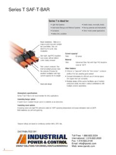
1 Series H SAF-T-BAR Conductor Bar The advanced " Series H" SAF-T-BAR system features integral insulated conductors to provide years of safe, economical, and trouble-free service. It Series H is ideal for: is designed for compact, low-cost installation, and minimum maintenance. Heavy duty cranes and monorails Wet locations Series H conductors are supplied in 20 foot lengths with factory installed Port authority equipment insulating covers. Joint fittings and covers are ordered separately. Dusty and dirty environments Environments conducive to electrical tracking Current Capacities Skin-tight insulation runs cooler, HC500 500 will not deform under clamp HC750 750. pressure. Standard insulation is HC1000 1000.
2 160o F (71o C). Alternative HC1500 1500. insulations are available Material Metal guideways assure positive All capacities: Aluminum with 304 Stainless Steel Contact tracking of collector shoe with Strip or without insulating cover Other available features Contact shoe with flat surface of sintered copper and graphite, self-lubricating to effective draw current to the collector. Heat sink collector heads available for high Flat contact surface for current draw. maximum Conductor wear; the stainless steel channel insert C. ompact mounting of Conductor in vertical or horizontal provides resistance to corrosion position without special parts or fittings. and electrical pitting. C. ollectors are available in either single or dual arm construction.
3 Single (L, LL), and pantograph dual-arm constructions (D, DD) are available. Atmospheric specifications In wet atmospheres, the system should be mounted on insulated hangers with the Conductor in the downturn position. In dirty and dusty atmospheres, mount the Conductor in the downturn position. If the atmosphere is likely to cause electrical over-surface tracking, choose hanger clamps with spool insulators rather than the standard coated hanger clamp. Insulating hanger option A plastic slide hanger is available as an alternative design. Insulating cover options Prefix A Standard rigid vinyl for cranes and hoists Suffix H Medium heat plastic to 260oF for cranes and hoists Suffix Fl High heat fiberglass to 375oF for cranes and hoists DISTRIBUTED BY: Toll Free: Fax: 70 Email: Web: Series H SAF-T-BAR Conductor Bar Characteristics Series H Conductor Bars are constructed of extruded aluminum with a stainless steel U shaped contact surface which guides collector shoe movement and minimizes collector shoe wear.
4 Bars are provided in four sizes: 500, 750, 1000, or 1500 Amp, each with "Standard Heat" rigid PVC insulation, "Medium Heat" Lexan, or "High Heat" fiberglass HC500 (HH) HC1000 (HH) HC1500 (HH) insulations are available by request. The standard rail length is 20 feet ( m). HC750 (HH). Bar Type: HC500 HC750 HC1000 HC1500. Nominal Current (amps) 1. 500 750 1000 1500. DC Resistance (ohms/ft) AC Impedance (ohms/ft at 60Hz) measured at " c/c Specifications AC Impedance (ohms/ft at 60Hz) measured at " c/c Wt lb/ft (kg/m) ( ) ( ) ( ) ( ). Max. Voltage (V) 600 600 600 600. Nominal Support Spacing (ft) 10 foot ( m). Standard Rail Length (ft) 20 ft ( m). Common 160O F ( C) at 260 PSI (Standard Heat Cover). Characteristics Maximum Rail Temperature 260O F ( C) at 260 PSI (Medium Heat Lexan Cover).
5 360O F ( C) at 260 PSI (High Heat Fiberglass Cover). Conductor Mounting Orientation Can be installed vertically or horizontally Curves Consult Factory 1. Nominal current is based on 30 C and is for 100% duty. Basic Series H Part Numbers 6. Phase Phase Joint Kit Power Power Feed Bar Conductor Conductor Med WT Joint Kit Med Heat Feed Expansion Gap Med Heat Type Std Heat 2 Heat 3 lb (kg) Std Heat 4 Lexan 4 Std Heat 4 Assemblies 5 Lexan 4. HC500 HC500X20 HC500 HHX20 ( ) HA500J HA500 HHJ HA500F HA500XG-8* HA500 HHF. HC750 HC750X20 HC750 HHX20 ( ) HA750J HA750 HHJ HA750F HA750XG-8* HA750 HHF. HC1000 HC1000X20 HC1000 HHX20 ( ) HA1000J HA1000 HHJ HA1000F HA1000XG-8* HA1000 HHF. HC1500 HC1500X20 HC1500 HHX20 ( ) HA1500J HA1500 HHJ HA1500F HA1500XG-8* HA1500 HHF.
6 2. Complete with "standard heat" cover (orange rigid PVC, 160 F heat distortion point, 260 psi, self extinguishing). 3. Complete with "medium heat" cover (red Lexan, 260 F heat distortion point, 260 psi, self extinguishing). 4. See Pg. 72. 5. Powerfeeds and Expansion kits: medium heat Lexan and high heat fiberglass versions are available - Contact Factory 6. End caps available for standard heat applications only - Part Nos.: HA500N, HA750N, HA1000N, HA1500N - See pg. 72. 2. Series H SAF-T-BAR Components Splice Joints The bolted Splice Joint assembly is comprised of two stacked spring plates located inside the hollow portion of the Conductor . Part No. Part No. Used on Bar: Std Heat Med Heat Wt (kg). HC500 HA500J HA500 HHJ ( ).
7 HC750 HA750J HA750 HHJ ( ). HC1000 HA1000J HA1000 HHJ ( ). HC1500 HA1500J HA1500 HHJ ( ). HA500J. HA750J. HA1000J. HA1500J. Powerfeed The Powerfeed supplies power to the bar and is inserted in place of the bar splice joint. Or it can be mounted at any point along the Conductor by cutting the bar and insulating cover. Used on Bar: Terminals Part No. Part No. Wt lb (kg). Std Heat Med Heat HC500 Two 350 MCM HA500F HA500 HHF ( ). HC750 Two 350 MCM HA750F HA750 HHF ( ). HC1000 Two 350 MCM HA1000F HA1000 HHF ( ). HC1500 Three 350 MCM-2 HA1500F HA1500 HHF ( ). End Cap End caps are to be driven onto the exposed ends of the conductors to completely insulate the bar. Cap is 4" (102 mm) long. Used on Bar: Part No.
8 Wt lb (kg). HC500 HA500N ( ). HC750 HA750N ( ). HC1000 HA1000N ( ). HC1500 HA1500N ( ). Isolation Joints Isolation joints are required for circuit segmentation and are comprised of an insulating angle with attachment hardware to secure and space the adjacent rails. Used on Bar: Part No. Wt lb (kg). HC500 HA1000IS ( ). HC750 HA1000IS ( ). HC1000 HA1000IS ( ). HC1500 HA1000IS ( ). 3. Series H SAF-T-BAR Components Hanger Clamps and Anchors Hanger clamp bracket should be attached to the runway beam by welding or bolting. Conductors should be spaced 5" (127 mm) inches apart, however, a minimum of " (89 mm) is acceptable. Hanger clamp brackets require 9/16" ( mm) holes for 1/2" hanger clamp bolts. To properly support the Conductor and to keep standard rail overhang to 24" (610 mm), space the first two brackets on 6' ( m) centers and all other brackets on 10' ( m) centers.
9 The "Anchor" is a non-sliding version of the hanger which provides a solid fixing point on the Conductor bar. Anchor clamp kit consists of an insulated keeper straddling each side of the standard hanger. The usual hanger bolt is replaced by a cup-point set screw that is tightened HA1000H/HA against the keeper plate at the desired anchor location. On HA1000H hangers, the set screw becomes the mounting bolt. ON HA1000K hangers, the set screw is threaded into the base of the insulator spool. HA1000PA anchors come with a drilled hole in the vertical stiffener. At the instal- lation site, a hole is drilled through the Conductor bar to accommodate a threaded rod. Threaded rod is captured by acorn nuts on both sides of the clamp.
10 Hanger Clamp Type 2 Usage Part No. 1 Wt lb (kg). Hanger, coated steel Normal atmospheres HA1000H ( ). Hanger, coated steel with insulator spool Wet atmospheres HA1000K ( ). HA1000K/KA In lieu of: HA1000P ( ). Hanger, Plastic HA1000H or HA1000K. Anchor, coated steel with anchor clamp kit Normal atmospheres HA1000HA ( ). Anchor, coated steel with insulator spool and Wet atmospheres HA1000KA ( ). anchor clamp kit Anchor, plastic with anchor clamp kit HA1000PA ( ). HA1000P/PA. 1. Suffix "A" indicates anchor options 2. All H Series components are available with stainless steel hardware, designated by the suffix "SS". Hanger Clamp Mounting 1/2" - 13 bolts 1/2" - 13 bolt 1/2" - 13 bolt 1/2" - 13 bolt 1/2" - 13 bolts ( ).