Transcription of Series: hydraulic-type control in pneumatic …
1 FABCO-AIR phone 1-352-373-3578 series : hydraulic -type control in pneumatic machineryAdding the control , rigidity and power of hydraulics to a pneumatic machineAdding the control , rigidity and power of hydraulics to a pneumatic machineControl with Air-Oil TanksAir-Oil tanks provide a nice alternative to hydraulic systems when precise cylinder motion is required. They cost less and take up far less space. No pumps. No noisy motors. No relief valves or the like. And of course, installation is a lot simpler combination with off-the-shelf air valves, air-oil tanks enable precise, smooth cylinder motion with absolute control using basic shop air pressure. Fabco-Air s Air-Oil tanks are available in single tank and space-saving double tank versions with bore ( ) sizes of 1-1/4 , 2 and 4 to suit most (3) pistons are simultaneously pressurized for the power stroke; one (1) drives the retract stroke.
2 At 90 psi, the three piston thrust will be over 5,000 pounds. More than enough for the job at hand. FABCO-AIR, Inc. speed and shock- As you know, we must make accommodations for the inertial and impact forces that will be released when our tooling breaks through the work piece. To capture these potentially destructive forces, and prevent damage to the power cylinder and tooling, an air-over-oil tank is incorporated in the circuit between the directional control valve and the cylinder return port. Single Tank Units - Single tanks are used when hydraulic control of the cylinder is required in one direction only. If there is any question as to the integrity of the piston seal, a double tank is recommended. Single Tank Units are also used as fluid storage tanks for boosters, hydraulic shock options, and other applications. Double Tank Units are used when hydraulic control of the cylinder is required in both direc-tions.
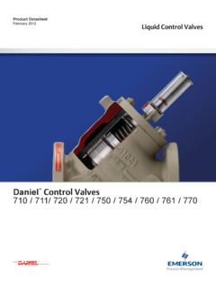
3 The one-piece heads that hold both tanks simplify mounting and save space. Using a single Air-Oil Tank with the power cylinder on an air press Let s assume we want to punch holes in a stack of laminations. We ll use one of Fabco-Air s Multi-Power air presses in this example. The power unit of the press is a 5 bore, force-multiplying air cyl-inder with three pistons. Fabco-Air Air-Oil Tanks: 2 Bore x 9 high Air SupplyPower CylinderFlow control ValveMufflerDirectional Control4-Way Air ValveSingle Tank Air-over- OilFigure 1. Air-over-oil shock control circuitBaffles separate the three pistons and have vents to atmosphereF55 series Press shown with customer toolingFABCO-AIR phone 1-352-373-3578 series : hydraulic -type control in pneumatic machineryFigure 2. Two-Speed work stroke with shock controlMufflerHow it works Fluid in the tank is used for the cylinder s return media only.
4 (Reference Figure 1, previous page.) Fluid flow and cylinder speed can be controlled by a needle or flow control valve. In our example we have chosen a flow control valve because we want to control the speed of the work stroke while allowing a full speed retract stroke. When the material shears and the cylinder tries to complete the stroke, the non-compressible fluid resists rapid movement. It catches the built-up forces, dissipating them before the cylinder can bottom out. Thus the piston won t pound on the piston stop. Two-Speed work stroke with shock control - With a slight modification to the circuit in Figure 1, using a sequence valve, a needle valve and a shut-off valve, our single air/oil tank provides us with 2-speed work stroke operation shown in Figure 2 sequence is as follows: 1. Rapid extend stroke to approach the Automatic switch to controlled rate when resistance is met and pressure builds up to the point where a Fabco-Air RV Sequence Valve actuates the 2-way shut-off valve forcing fluidflow through the speed controlling needle valve.
5 (See page 5 for RV info)3. Fluid catches the cylinder motion, thus controlling the shock that could otherwise Automatic return to rapid rate on the Cylinder Retract for using Air-Oil Systems -1 The best control is achieved by installing the speed control valves so that the fluid being forced out of the cylinder is being controlled. 2 The piping between the cylinder and the speed controlling valve should be rigid enough to maintain the required rigidity of the It is best to mount the tanks so that the bottoms of the tanks are higher than the cylinder. Cylinder ports should be up with piping running as straight as pos-sible to the tanks. This aids in purging the cylinder of air, by allowing the air to rise through the piping and into the tank where it will fluid through the translucent fiberglass1 The highest fluid level should be kept reasonably near the top baffle to avoid excessive air usage, provid-ing the quickest cycle reversal, and to allow for possible fluid If the fluid levels in the tanks become unbalanced, the fluid is bypassing the cylinder s piston seal.
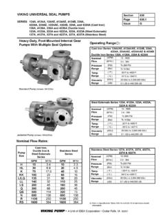
6 This can occur in a new cylinder with U-Cups designed for air service or side loading on the piston rod. In old systems the bypass can be a result of seal and cylinder wear, seal shrinkage, or other reasons. A crossover valve can allow for tank balancing. (See Figure 4.)3. Fluid aeration and foaming can reduce intended cylinder control and make its operation mushy. Properly designed air-oil tanks have special baffling top and bottom which eliminates such disturbance. (Figure 3.)FillPortFlow PortDrainPortFlowPortQuiet zonebelow baffleplate forsediment tosettle outBrass baffleplates, tube, &spacers, top &bottomCustom moldedBuna-N tubesealBaffles force fluid orair to sides of tank,eliminating surfacedisturbance,aeration & foamingUsableOilCapacityTranslucentfiber glasstubeFigure 3. Fabco-Air Single tank construction highlighting the engineered baffle systemPage 2 FABCO-AIR phone 1-352-373-3578 series : hydraulic -type control in pneumatic Add hydraulic power with a pneumatic boosterCombining an Air-Oil Tank with a pressure booster provides a convenient, low cost way of adding the control , rigidity, and power of hydraulics to an air powered machine.
7 Fabco-Air Multi-Power Boosters use basic shop air to raise the pressure of another gas or liquid. They are compact and versatile finding use in numerous applications such as clamping, shearing, pressing, crimping, bending, testing, and many more. Two considerations- (1) When relatively small volumes of high-pressure fluid are called for intermittently, boosters show obvi-ous advantages over continuously running hydraulic systems.(2) For applications where high pressure must be maintained for prolonged times, boosters are ideal. After the booster strokes, there is no further energy input required and no heat build booster can be mounted in almost any convenient location, and most of its control valves are installed in the low-pressure circuit where lower cost components save costs over Air-Oil Tanks -Earlier we discussed controlling cylinder speed in one direction only.
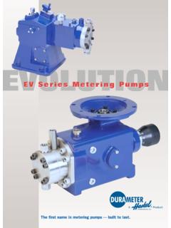
8 When control is required in both directions, two air-oil tanks are needed. As you can see from the circuit shown below, double Air-Oil Tanks used in conjunction with two flow control valves enables hydraulic control with one speed in each speed in two (2) directionsCylinderDoubleAir - OilTanksAir SupplyDirectional ControlValve 4-Way AirFlowControlMufflerCrossoverand shut offprovide easybalancing oftank levelsBi-Directional, Two-Speed Stop & HoldHere s another helpful circuit showing double Air-Oil Tanks used with shut-off valves & needle valves to provide:(1) Stop & hold in either direction at any point in cylinder travel.(2) Choice of rapid or control rate in either di-rection at any point of cylinder 5. Bi-directional, 2-speed, stop & holdHow they work -The input is shop air, or any compatible gas, up to 150 psi; the output can be oil, liquid, air, or gas pressurized to 500 psi maximum.
9 Multiple pistons compress the oil or fluid in the output end of the booster. Check valves insure the direction of fluid flow. Figure 6. Function of 2-stage Pressure BoosterPistonSealsPistonBaffleCenterShaf tBaffleSealAir into MultiplePistons for Power Stroke. 30 psi Minimum InputAir into SinglePiston for ResetStrokePilotWasherPistonStopCap EndPlugCheck ValveNot FurnishedHigh (Boosted) Pressure Output 500 psi MaximumCheck Valve Not FurnishedGravity Feed Oil or FluidAtmospheric Pressure: Air or GasDrivingEndOutputEndNutPistonTubeSealI n Figure 6 above we show only two (2) pistons. But Fabco-Air boosters can have as many as five (5) pistons driving the 3 FABCO-AIR phone 1-352-373-3578 series : hydraulic -type control in pneumatic machinerySizing boosters -By selecting the proper combination of bore size, stroke, power factor (determined by number of pis-tons) and regulating the input air pressure, the exact output pressure and required volume can be achieved and maintained.
10 WorkCylindersDriving EndOutput EndBA series BoosterRegulated Supply Controls FinalOutput Pressure of BoosterAir/OilTankAtmosphereGagePilot OperatedCheck Valve4 Way control ValveAir/Oil TankAtmosphereRegulated Supply Controls FinalOutput Pressure of Booster4 Way control ValveGageDriving EndOutput EndCheck ValveCheck ValveSensorsBA series Booster withOption EMagnetic Pistonfor PistonPosition SensingVersatility -Since it is a basic booster without controls built-in, it can be adapted and controlled to perform a wide variety of applications. Fabco-Air boosters are not limited to cylinder applications. They may be used wherever a small volume of high-pressure media is BA series is built for use on systems in which the input to the booster will be gravity fed (no pres-sure) fluid or atmospheric pressure gas. It requires a 4-way air valve for operation. Porting is provided on the booster for the multiple piston power stroke and single piston reset stroke.